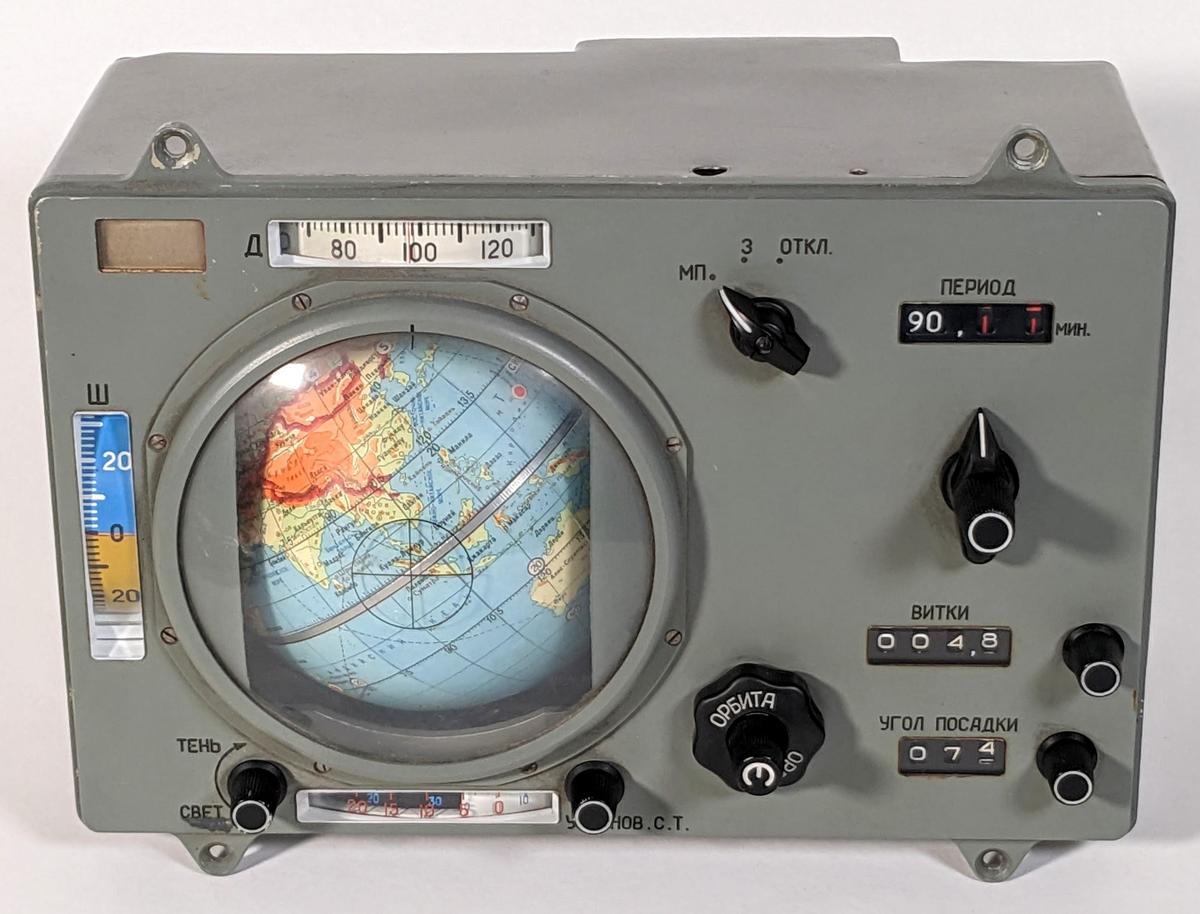
One of the most interesting navigation instruments onboard Soyuz spacecraft was the Globus INK,1 which used a rotating globe to indicate the spacecraft's position above the Earth. This electromechanical analog computer used an elaborate system of gears, cams, and differentials to compute the spacecraft's position. The globe rotates in two dimensions: it spins end-over-end to indicate the spacecraft's orbit, while the globe's hemispheres rotate according to the Earth's daily rotation around its axis.2 The spacecraft's position above the Earth was represented by the fixed crosshairs on the plastic dome. The Globus also has latitude and longitude dials next to the globe to show the position numerically, while the light/shadow dial below the globe indicated when the spacecraft would enter or leave the Earth's shadow.
The INK-2S "Globus" space navigation indicator.
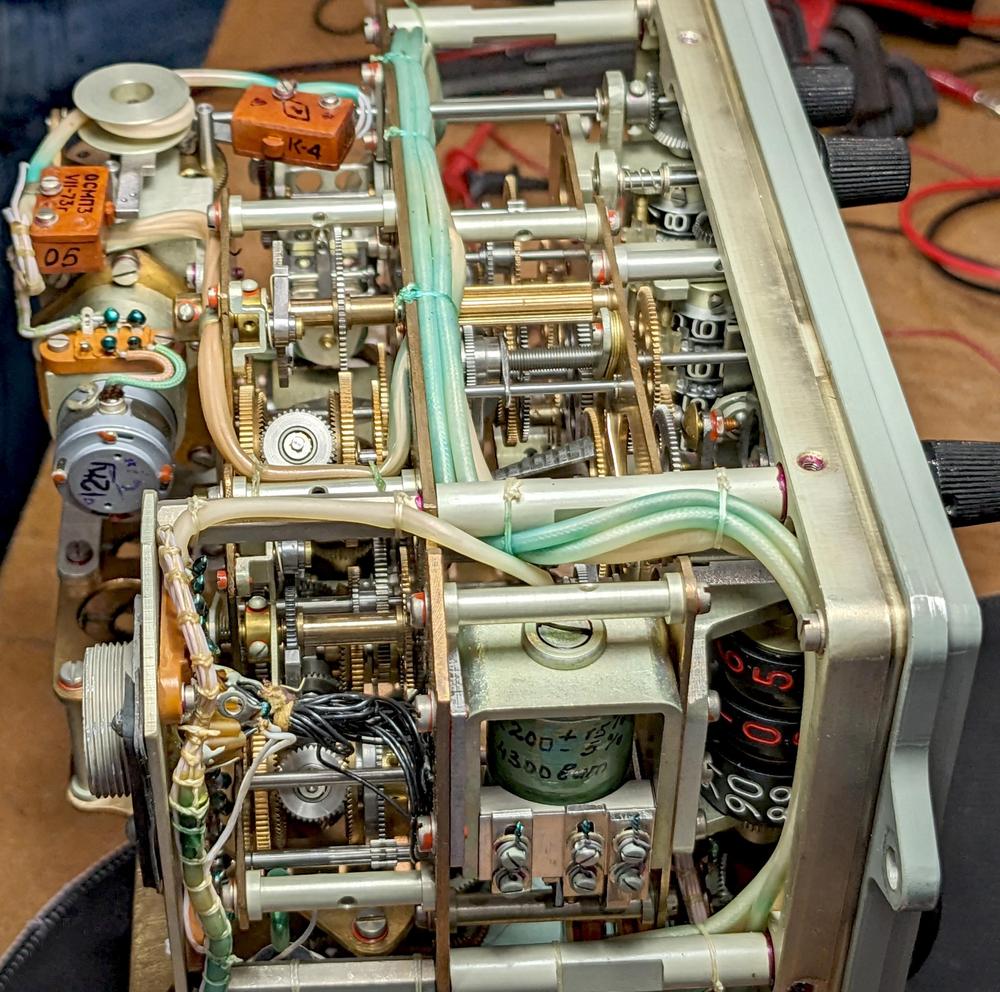
Opening up the Globus reveals that it is packed with complicated gears and mechanisms. It's amazing that this mechanical technology was used from the 1960s into the 21st century. But what are all those gears doing? How can orbital functions be implemented with gears? To answer these questions, I reverse-engineered the Globus and traced out its system of gears.
The Globus with the case removed, showing the complex gearing inside.
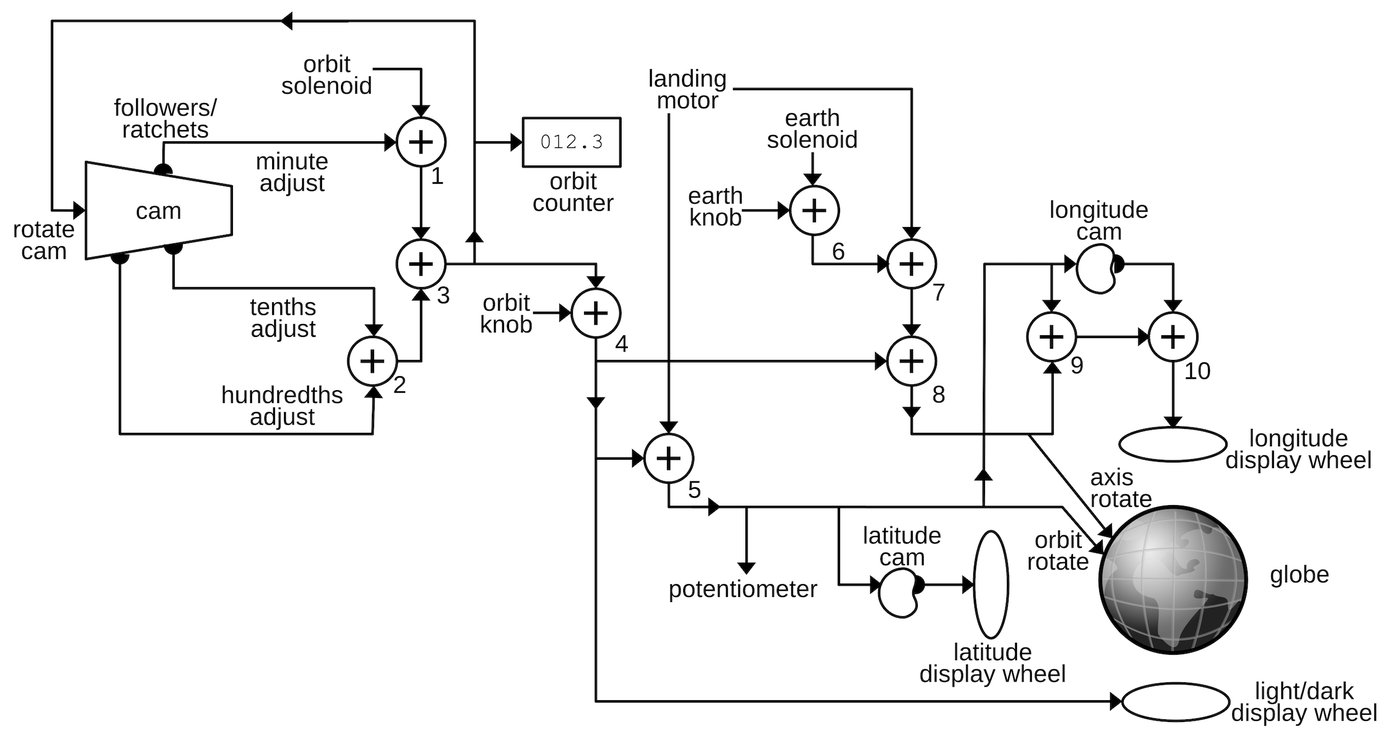
The diagram below summarizes my analysis. The Globus is an analog computer that represents values by rotating shafts by particular amounts. These rotations control the globe and the indicator dials. The flow of these rotational signals is shown by the lines on the diagram. The computation is based around addition, performed by ten differential gear assemblies. On the diagram, each "⨁" symbol indicates one of these differential gear assemblies. Other gears connect the components while scaling the signals through various gear ratios. Complicated functions are implemented with three specially-shaped cams. In the remainder of this blog post, I will break this diagram down into functional blocks and explain how the Globus operates.
This diagram shows the interconnections of the gear network in the Globus.
For all its complexity, though, the functionality of the Globus is pretty limited. It only handles a fixed orbit at a specific angle, and treats the orbit as circular. The Globus does not have any navigation input such as an inertial measurement unit (IMU). Instead, the cosmonauts configured the Globus by turning knobs to set the spacecraft's initial position and orbital period. From there, the Globus simply projected the current position of the spacecraft forward, essentially dead reckoning.
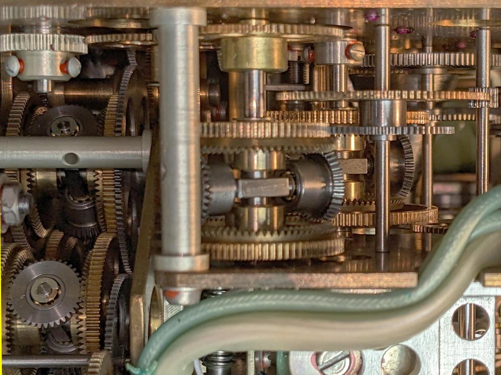
A closeup of the gears inside the Globus.
The globe
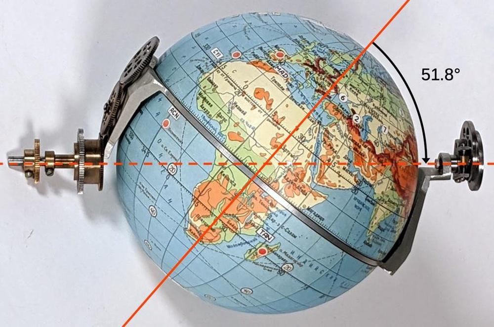
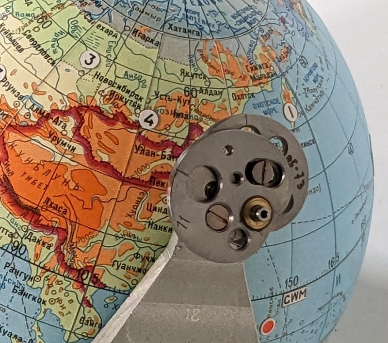
On seeing the Globus, one might wonder how the globe is rotated. It may seem that the globe must be free-floating so it can rotate in two axes. Instead, a clever mechanism attaches the globe to the unit. The key is that the globe's equator is a solid piece of metal that rotates around the horizontal axis of the unit. A second gear mechanism inside the globe rotates the globe around the North-South axis. The two rotations are controlled by concentric shafts that are fixed to the unit. Thus, the globe has two rotational degrees of freedom, even though it is attached at both ends.
The photo below shows the frame that holds and controls the globe. The dotted axis is fixed horizontally in the unit and rotations are fed through the two gears at the left. One gear rotates the globe and frame around the dotted axis, while the gear train causes the globe to rotate around the vertical polar axis (while the equator remains fixed).
The axis of the globe is at 51.8° to support that orbital inclination.
The angle above is 51.8° which is very important: this is the inclination of the standard Soyuz orbit. As a result, simply rotating the globe around the dotted line causes the crosshair to trace the orbit.3 Rotating the two halves of the globe around the poles yields the different paths over the Earth's surface as the Earth rotates. An important consequence of this design is that the Globus only supports a circular orbit at a fixed angle.
Differential gear mechanism
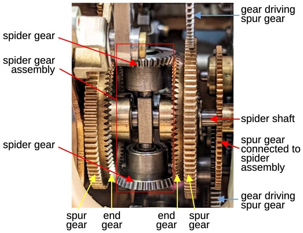
The primary mathematical element of the Globus is the differential gear mechanism, which can perform addition or subtraction. A differential gear takes two rotations as inputs and produces the (scaled) sum of the rotations as the output. The photo below shows one of the differential mechanisms. In the middle, the spider gear assembly (red box) consists of two bevel gears that can spin freely on a vertical shaft. The spider gear assembly as a whole is attached to a horizontal shaft, called the spider shaft. At the right, the spider shaft is attached to a spur gear (a gear with straight-cut teeth). The spider gear assembly, the spider shaft, and the spider's spur gear rotate together as a unit.
Diagram showing the components of a differential gear mechanism.
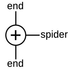
At the left and right are two end gear assemblies (yellow). The end gear is a bevel gear with angled teeth to mesh with the spider gears. Each end gear is locked to a spur gear and these gears spin freely on the horizontal spider shaft. In total, there are three spur gears: two connected to the end gears and one connected to the spider assembly. In the diagrams, I'll use the symbol below to represent the differential gear assembly: the end gears are symmetric on the top and bottom, with the spider shaft on the side. Any of the three spur gears can be used as an output, with the other two serving as inputs.
The symbol for the differential gear assembly.
To understand the behavior of the differential, suppose the two end gears are driven in the same direction at the same rate, say upwards.4 These gears will push on the spider gears and rotate the spider gear assembly, with the entire differential rotating as a fixed unit. On the other hand, suppose the two end gears are driven in opposite directions. In this case, the spider gears will spin on their shaft, but the spider gear assembly will remain stationary. In either case, the spider gear assembly motion is the average of the two end gear rotations, that is, the sum of the two rotations divided by 2. (I'll ignore the factor of 2 since I'm ignoring all the gear ratios.) If the operation of the differential is still confusing, this vintage Navy video has a detailed explanation.
The controls and displays
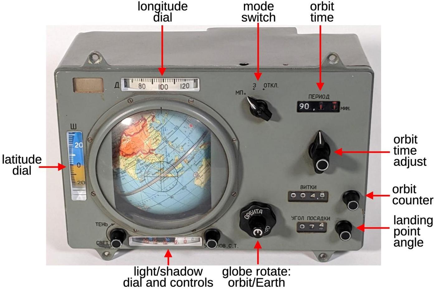
The diagram below shows the controls and displays of the Globus. The rotating globe is the centerpiece of the unit. Its plastic cover has a crosshair that represents the spacecraft's position above the Earth's surface. Surrounding the globe itself are dials that show the longitude, latitude, and the time before entering light and shadow. The cosmonauts manually initialize the globe position with the concentric globe rotation knobs: one rotates the globe along the orbital path while the other rotates the hemispheres. The mode switch at the top selects between the landing position mode, the standard Earth orbit mode, and turning off the unit. The orbit time adjustment configures the orbital time period in minutes while the orbit counter below it counts the number of orbits. Finally, the landing point angle sets the distance to the landing point in degrees of orbit.
The Globus with the controls labeled.
Computing the orbit time
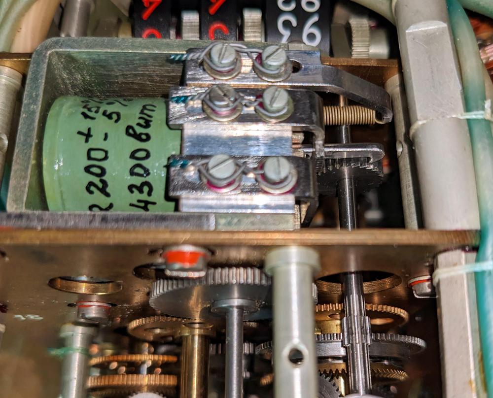
The primary motion of the Globus is the end-over-end rotation of the globe showing the movement of the spacecraft in orbit. The orbital motion is powered by a solenoid at the top of the Globus that receives pulses once a second and advances a ratchet wheel (video).5 This wheel is connected to a complicated cam and differential system to provide the orbital motion.
The orbit solenoid (green) has a ratchet that rotates the gear to the right. The shaft connects it to differential gear assembly 1 at the bottom right.
Each orbit takes about 92 minutes, but the orbital time can be adjusted by a few minutes in steps of 0.01 minutes6 to account for changes in altitude. The Globus is surprisingly inflexible and this is the only orbital parameter that can be adjusted.7 The orbital period is adjusted by the three-position orbit time switch, which points to the minutes, tenths, or hundredths. Turning the central knob adjusts the indicated period dial.
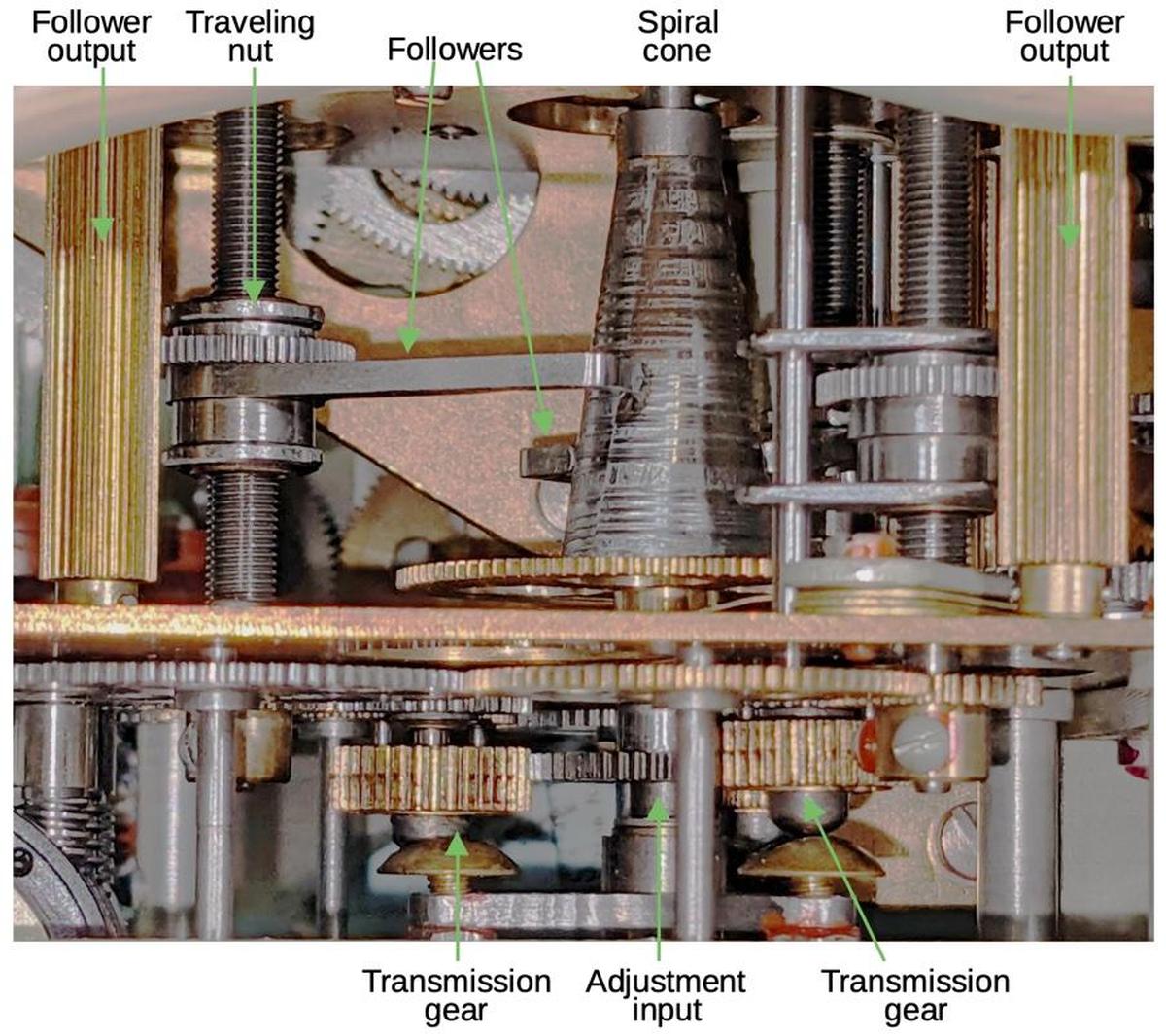
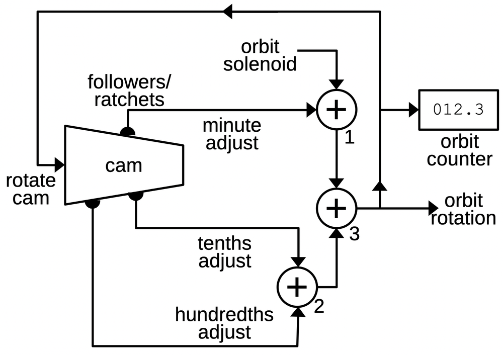
The problem is how to generate the variable orbital rotation speed from the fixed speed of the solenoid. The solution is a special cam, shaped like a cone with a spiral cross-section. Three followers ride on the cam, so as the cam rotates, the follower is pushed outward and rotates on its shaft. If the follower is near the narrow part of the cam, it moves over a small distance and has a small rotation. But if the follower is near the wide part of the cam, it moves a larger distance and has a larger rotation. Thus, by moving the follower to a particular point on the cam, the rotational speed of the follower is selected. One follower adjusts the speed based on the minutes setting with others for the tenths and hundredths of minutes.
A diagram showing the orbital speed control mechanism. The cone has three followers, but only two are visible from this angle. The "transmission" gears are moved in and out by the outer knob to select which follower is adjusted by the inner knob.
Of course, the cam can't spiral out forever. Instead, at the end of one revolution, its cross-section drops back sharply to the starting diameter. This causes the follower to snap back to its original position. To prevent this from jerking the globe backward, the follower is connected to the differential gearing via a slip clutch and ratchet. Thus, when the follower snaps back, the ratchet holds the drive shaft stationary. The drive shaft then continues its rotation as the follower starts cycling out again. Each shaft output is accordingly a (mostly) smooth rotation at a speed that depends on the position of the follower.
A cam-based system adjusts the orbital speed using three differential gear assemblies.
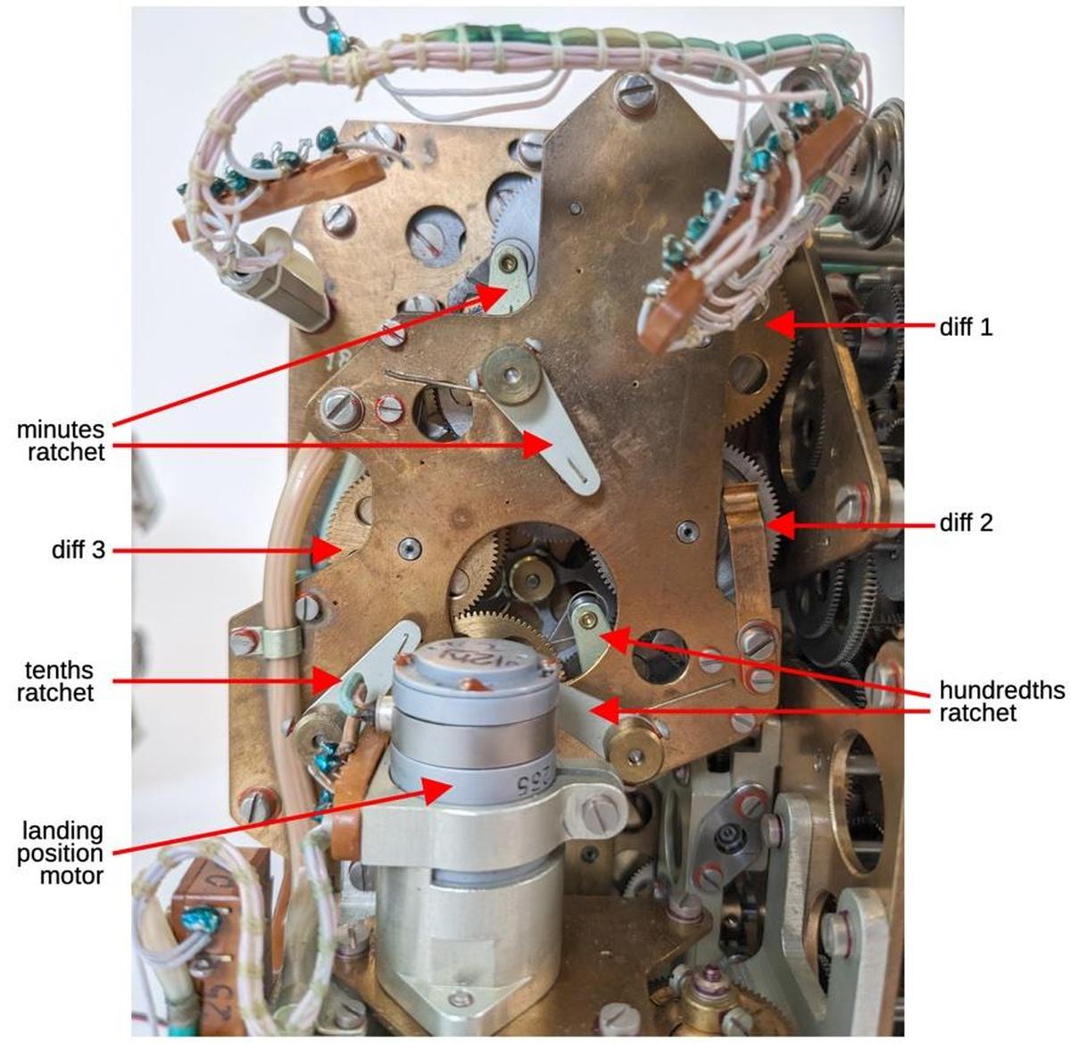
The three adjustment signals are scaled by gear ratios to provide the appropriate contribution to the rotation. As shown above, the adjustments are added to the solenoid output by three differentials to generate the orbit rotation signal, output from differential 3.8 This signal also drives the odometer-like orbit counter on the front of the Globus. The diagram below shows how the components are arranged, as viewed from the back.
A back view of the Globus showing the orbit components.
Displaying the orbit rotation
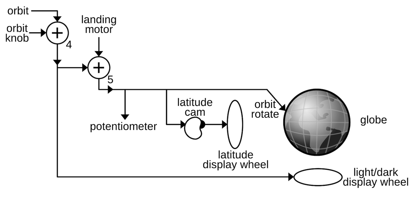
Since the Globus doesn't have any external position input such as inertial guidance, it must be initialized by the cosmonauts. A knob on the front of the Globus provides manual adjustment of the orbital position. Differential 4 adds the knob signal to the orbit output discussed above.
The orbit controls drive the globe's motion.
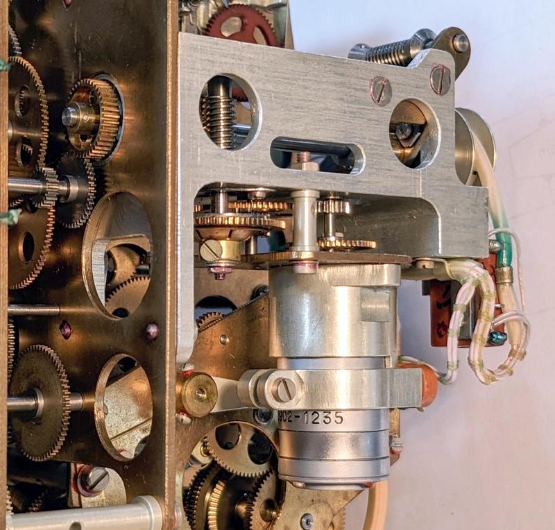
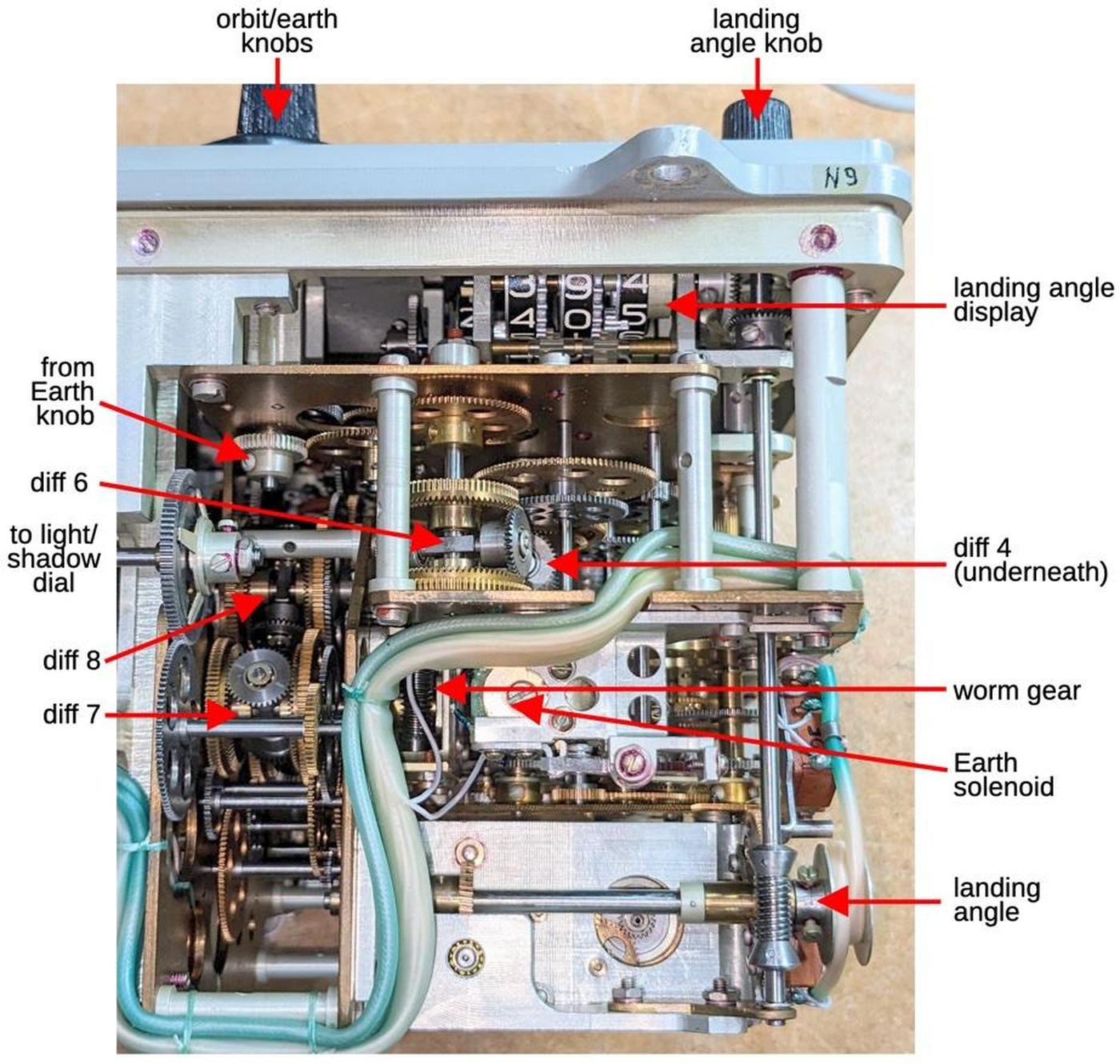
The Globus has a "landing point" mode where the globe is rapidly rotated through a fraction of an orbit to indicate where the spacecraft would land if the retro-rockets were fired. Turning the mode switch caused the globe to rotate until the landing position was under the crosshairs and the cosmonauts could evaluate the suitability of this landing site. This mode is implemented with a landing position motor that provides the rapid rotation. This motor also rotates the globe back to the orbital position. The motor is driven through an electronics board with relays and a transistor, controlled by limit switches. I discussed the electronics in a previous post so I won't go into more details here. The landing position motor feeds into the orbit signal through differential 5, producing the final orbit signal.
The landing position motor and its associated gearing. The motor speed is geared down and then fed through a worm gear (upper center).
The orbit signal from differential 5 is used in several ways. Most importantly, the orbit signal provides the end-over-end rotation of the globe to indicate the spacecraft's travel in orbit. As discussed earlier, this is accomplished by rotating the globe's metal frame around the horizontal axis. The orbital signal also rotates a potentiometer to provide an electrical indication of the orbital position to other spacecraft systems.
The light/shadow indicator
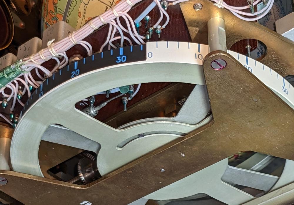
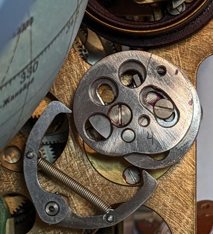
Docking a spacecraft is a tricky endeavor, best performed in daylight, so it is useful to know how much time remains until the spacecraft enters the Earth's shadow. The light/shadow dial under the globe provides this information. This display consists of two nested wheels. The outer wheel is white and has two quarters removed. Through these gaps, the partially-black inner wheel is exposed, which can be adjusted to show 0% to 50% dark. This display is rotated by the orbital signal, turning half a revolution per orbit. As the spacecraft orbits, this dial shows the light/shadow transition and the time to the transistion.9
The light/shadow indicator, viewed from the underside of the Globus. The shadow indicator has been set to 35% shadow. Near the hub, a pin restricts motion of the inner wheel relative to the outer wheel.
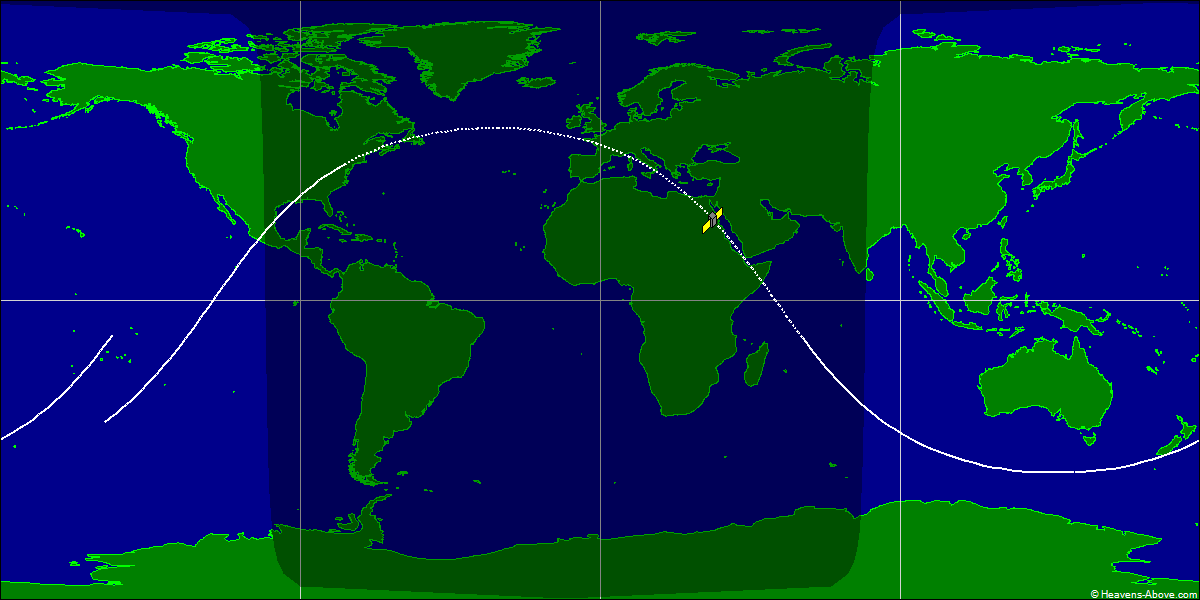
You might expect the orbit to be in the dark 50% of the time, but because the spacecraft is about 200 km above the Earth's surface, it will sometimes be illuminated when the surface of the Earth underneath is dark.10 In the ground track below, the dotted part of the track is where the spacecraft is in the Earth's shadow; this is considerably less than 50%. Also note that the end of the orbit doesn't match up with the beginning, due to the Earth's rotation during the orbit.
Ground track of an Apollo-Soyuz Test Project orbit, corresponding to this Globus. Image courtesy of heavens-above.com.
The latitude indicator
The latitude indicator to the left of the globe shows the spacecraft's latitude. The map above shows how the latitude oscillates between 51.8°N and 51.8°S, corresponding to the launch inclination angle. Even though the path around the globe is a straight (circular) line, the orbit appears roughly sinusoidal when projected onto the map.11 The exact latitude is a surprisingly complicated function of the orbital position.12 This function is implemented by a cam that is attached to the globe. The varying radius of the cam corresponds to the function. A follower tracks the profile of the cam and rotates the latitude display wheel accordingly, providing the non-linear motion.
A cam is attached to the globe and rotates with the globe.
The Earth's rotation
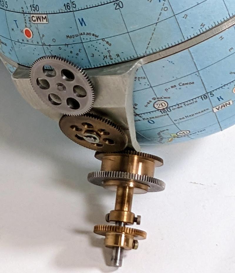
The second motion of the globe is the Earth's daily rotation around its axis, which I'll call the Earth rotation. The Earth rotation is fed into the globe through the outer part of a concentric shaft, while the orbital rotation is provided through the inner shaft. The Earth rotation is transferred through three gears to the equatorial frame, where an internal mechanism rotates the hemispheres. There's a complication, though: if the globe's orbital shaft turns while the Earth rotation shaft remains stationary, the frame will rotate, causing the gears to turn and the hemispheres to rotate. In other words, keeping the hemispheres stationary requires the Earth shaft to rotate with the orbit shaft.
A closeup of the gear mechanisms that drive the Globus, showing the concentric shafts that control the two rotations.
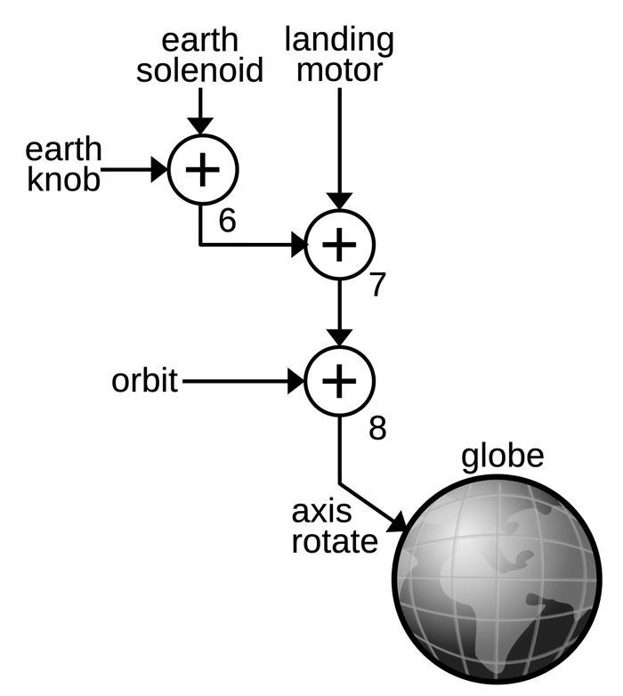
The Globus solves this problem by adding the orbit rotation to the Earth rotation, as shown in the diagram below, using differentials 7 and 8. Differential 8 adds the normal orbit rotation, while differential 7 adds the orbit rotation due to the landing motor.14
The mechanism to compute the Earth's rotation around its axis.
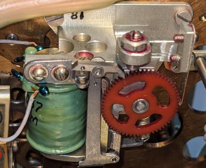
The Earth motion is generated by a second solenoid (below) that is driven with one pulse per second.13 This motion is simpler than the orbit motion because it has a fixed rate. The "Earth" knob on the front of the Globus permits manual rotation around the Earth's axis. This signal is combined with the solenoid signal by differential 6. The sum from the three differentials is fed into the globe, rotating the hemispheres around their axis.
This solenoid, ratchet, and gear on the underside of the Globus drive the Earth rotation.
The solenoid and differentials are visible from the underside of the Globus. The diagram below labels these components as well as other important components.
The underside of the Globus.
The longitude display
The longitude cam and the followers that track its radius.
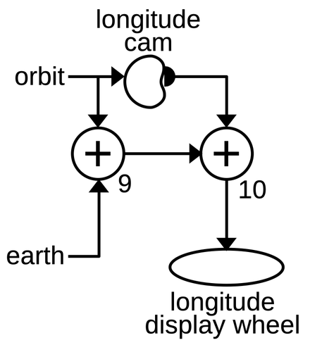
The longitude display is more complicated than the latitude display because it depends on both the Earth rotation and the orbit rotation. Unlike the latitude, the longitude doesn't oscillate but increases. The longitude increases by 360° every orbit according to a complicated formula describing the projection of the orbit onto the globe. Most of the time, the increase is small, but when crossing near the poles, the longitude changes rapidly. The Earth's rotation provides a smaller but steady negative change to the longitude.
The computation of the longitude.
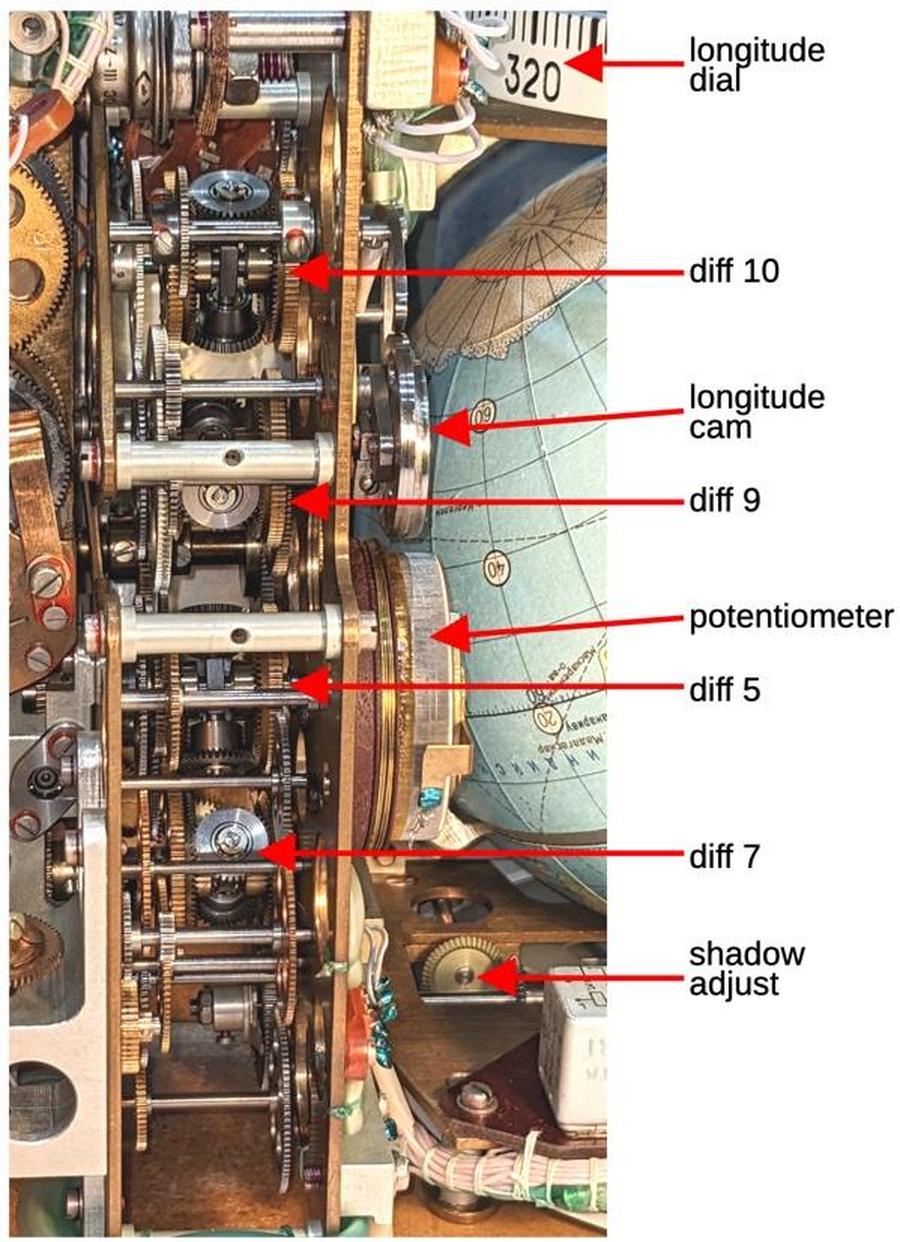
The diagram above shows how the longitude is computed by combining the Earth rotation with the orbit rotation. Differential 9 adds the linear effect of the orbit on longitude (360° per orbit) and subtracts the effect of the Earth's rotation (360° per day). The nonlinear effect of the orbit is computed by a cam that is rotated by the orbit signal. The shape of the cam is picked up and fed into differential 10, computing the longitude that is displayed on the dial. The differentials, cam, and dial are visible from the back of the Globus (below).
A closeup of the differentials from the back of the Globus.
The time-lapse video below demonstrates the behavior of the rotating displays. The latitude display on the left oscillates between 51.8°N and 51.8°S. The longitude display at the top advances at a changing rate. Near the equator, it advances slowly, while it accelerates near the poles. The light/shadow display at the bottom rotates at a constant speed, completing half a revolution (one light/shadow cycle) per orbit.
Conclusions
The Globus INK is a remarkable piece of machinery, an analog computer that calculates orbits through an intricate system of gears, cams, and differentials. It provided astronauts with a high-resolution, full-color display of the spacecraft's position, way beyond what an electronic space computer could provide in the 1960s.
The drawback of the Globus is that its functionality is limited. Its parameters must be manually configured: the spacecraft's starting position, the orbital speed, the light/shadow regions, and the landing angle. It doesn't take any external guidance inputs, such as an IMU (inertial measurement unit), so it's not particularly accurate. Finally, it only supports a circular orbit at a fixed angle. While a more modern digital display lacks the physical charm of a rotating globe, the digital solution provides much more capability.
I recently wrote blog posts providing a Globus overview and the Globus electronics. Follow me on Twitter @kenshirriff or RSS for updates. I've also started experimenting with Mastodon recently as @[email protected]. Many thanks to Marcel for providing the Globus. I worked on this with CuriousMarc, so check out his Globus videos.
Notes and references
from Hacker News https://ift.tt/jrBfxFD
No comments:
Post a Comment
Note: Only a member of this blog may post a comment.