God...dammit
Background
It's hard to see a child outside today without some kind of iDevice pumping high fidelity 192kbps stereo lossless audio into their shiny white headphones, but BACK IN MY DAY, the iPod hadn't been invented yet. Pickings were slim. Walkmen were outdated, CD players were pricey and would skip if bumped around despite their ESP features, MiniDisk was another stillborn Sony format, and MP3 players were still ugly and ridiculously expensive (at least Apple fixed the ugly part).
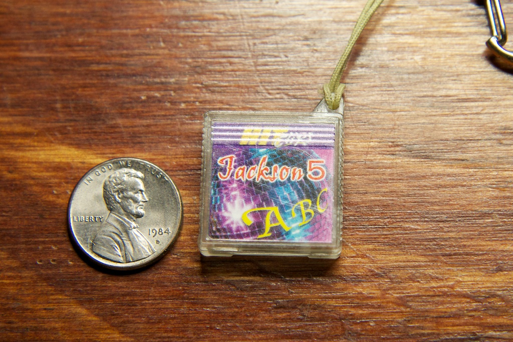
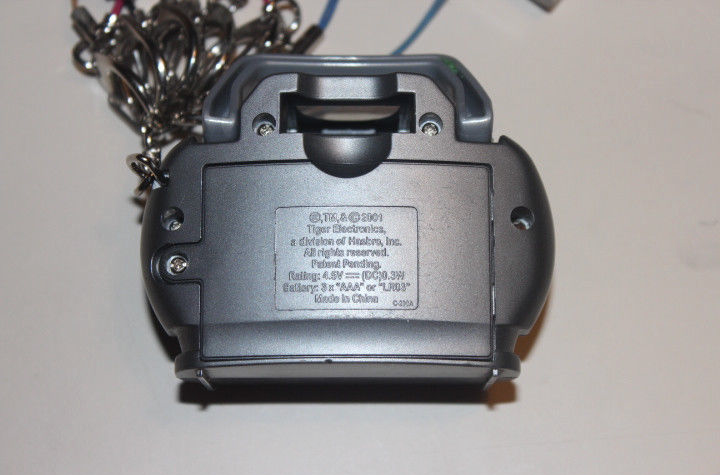
Thus, Tiger Electronics, pioneers in the high tech market of McDonald's Happy Meal toys, invented "Hit Clips"
Hit Clips were small cheap digital audio players that could play music off of little plastic cartridges. The audio was mono, sounded terrible, and only included a 60 second sample of a song.
Better hold on to that patent Tiger...
Still, the songs were officially licensed and included bands like The Backstreet Boys, Aaron Carter, Sugar Ray, and ...Dreamstreet
The 00s were a very strange time for all of us...
Anywho, while helping my 17 year old cousin move some furniture, we came across a large collection of hit clip cartridges, but no player. Struck with a wave of nostalgia, I asked if I could take one to do a tear down.
Thus this post.
Teardown
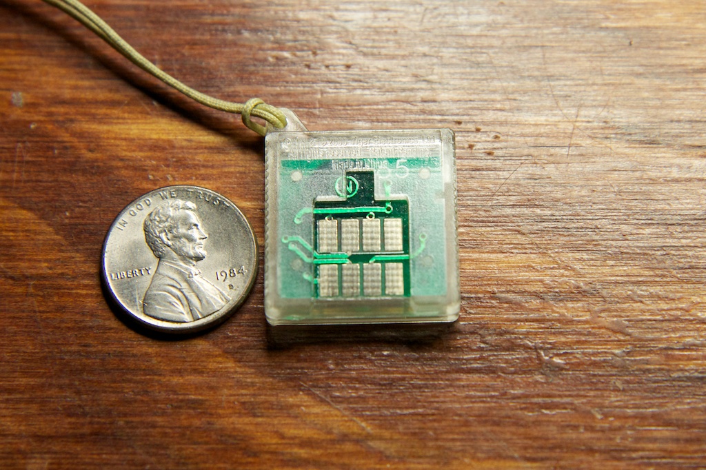
The hit clip cartridge has 8 metal contacts on the back:
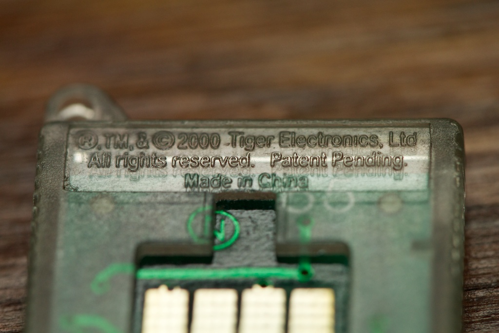
Taking it apart, I was hoping to find some identifiable piece of hardware, but instead found the chip-on-board construction that is so popular with super-low-cost low-power electronics along with a few discrete components.
Under this blob of epoxy is a wire-bonded chip of silicon. The song is likely hard coded directly into the silicon wafer rather than being programmed there after the fact using flash or OTP memory. It's cheaper that way if you make enough units.
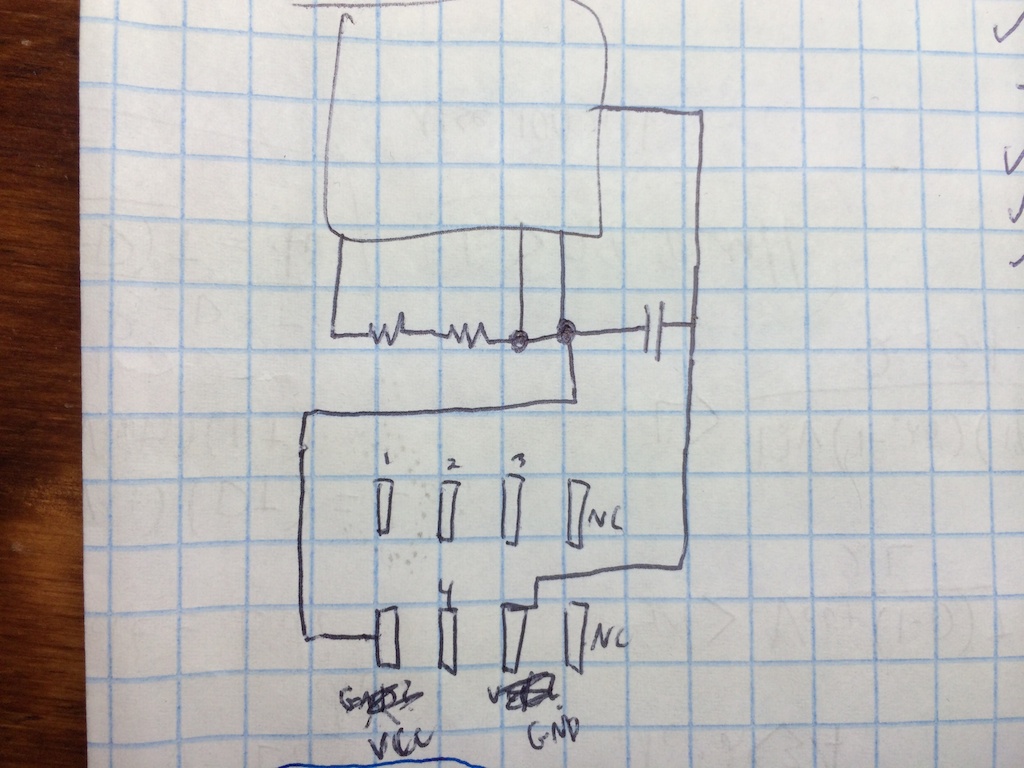
This didn't give me a whole lot to work from, but assuming the capacitor is a bypass capacitor (decent assumption), I at least had some idea of how to power the thing. Poking around for a bit gave me this schematic:
I'm not sure what the two No Connect pins do, but apparently there was a version of the Hit Clip that allowed music to be recorded to special cartridges, so I'm guessing they have something to do with that.
I wasn't sure how much voltage the part needed, but a quick search on Ebay gave me some idea:
3 AAAs means 4.5V. Also, can you believe people are bidding $40+ for these things?
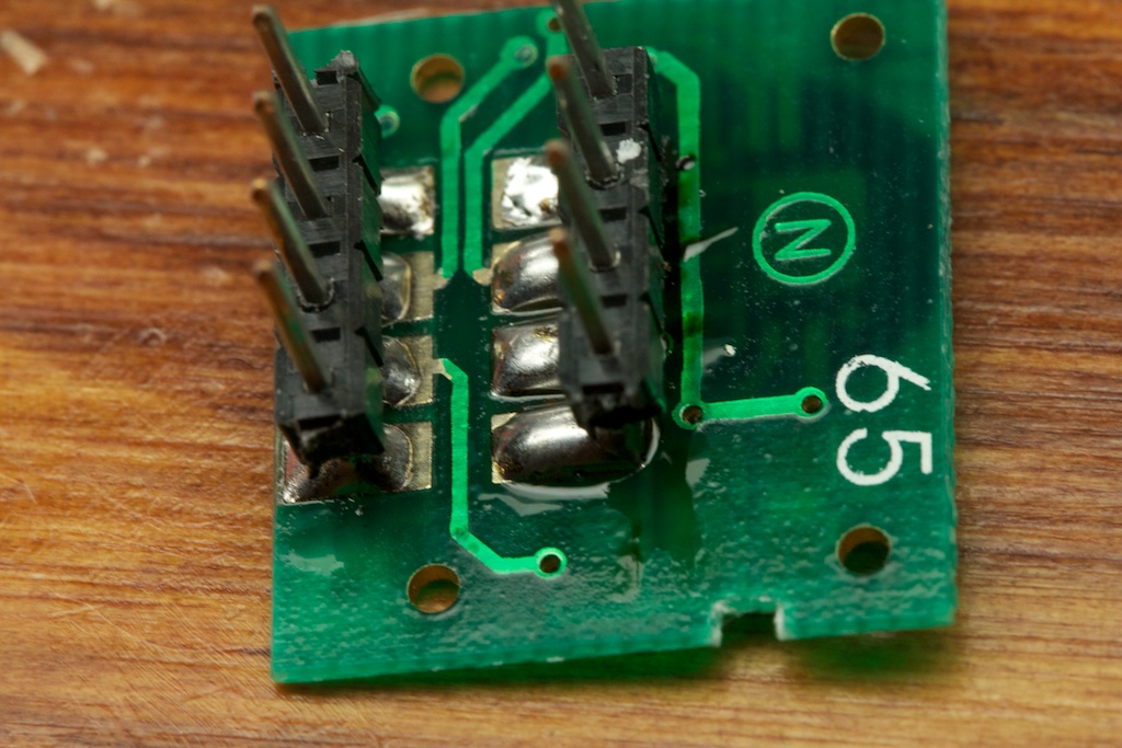
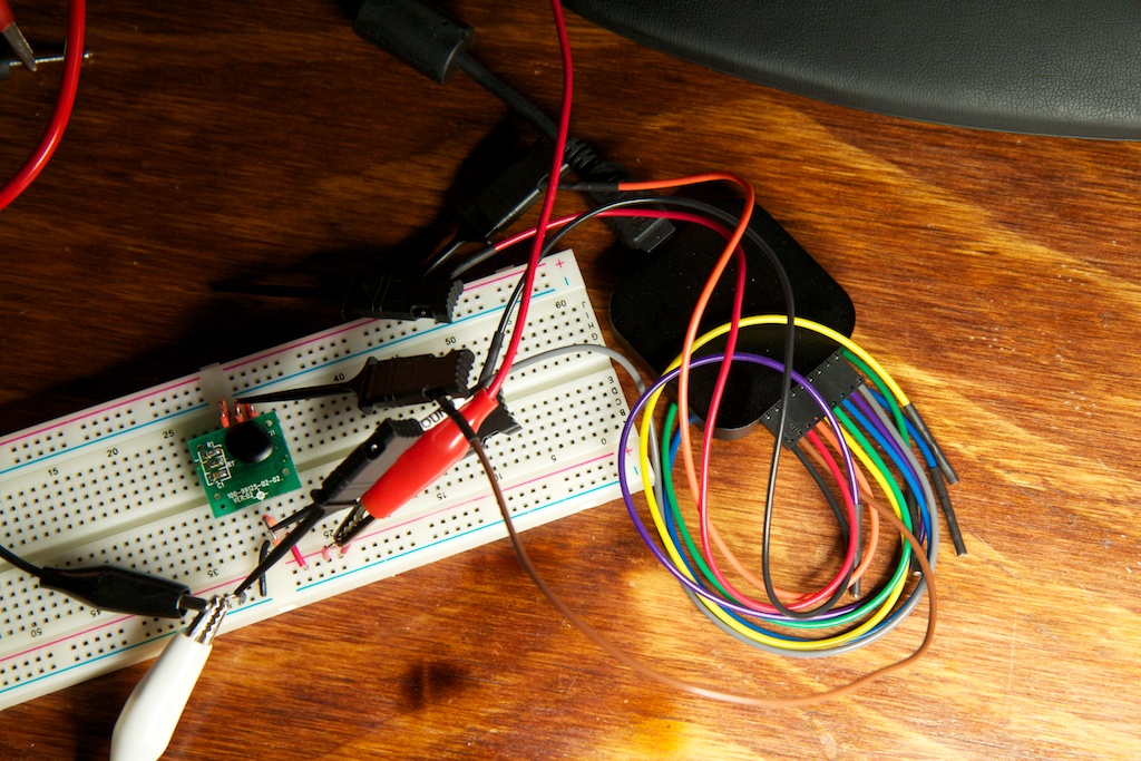
Before I could get serious about debugging, I needed some way to connect traces to the board easily. I ended up soldering on some header pins and plugging it into a breadboard:
My original assumption was that the bottom-left pin was ground as it connected to the mystery chip more times than the other power-pin. You'll note the scratch-outs indicate that I was wrong. In that configuration, the chip drew 200+mA during the half-second that I left it connected. Presumably there's a reverse bias protection diode that I was blowing up.
Swapping the power pins around, the current started at around 280 A before dropping to zero.
Convinced that I had it right, I moved to the other pins. There were four pins to chose from and a voltage measurement showed me that two of them were at the 4.5V rail while the other two were settled close to 0V.
| 1 | High |
| 2 | Low |
| 3 | High |
| 4 | Low |
Since I had already identified my two power pins, I had to assume that these four pins were used for data somehow and that the two high pins had internal pull up resistors.
Connecting Pin1 to ground sinks about 12mA from that pin. 12mA is much to high to be from a simple pull-up resistor. My guess is that it's some kind of output pin to tell the player that the cartridge is inserted all the way. I decided to leave it alone and move on to Pin 3.
Connecting Pin 3 to ground caused the circuit's current draw to rise from zero up to 300 A. Removing this short did nothing to change the current increase although it did settle down after about 60 seconds.
This is when I knew I was on to something. 60 seconds of current draw meant that this part was outputting its music sample! I was expecting the player to need to do something more complicated like pull bytes of music off the cartridge over a SPI bus or at least provide a clock source, but it turns out that the cartridge can handle that all by itself. I'm guessing that the two on-board series resistors are used for fine-tuning its internal clock source after the chip has been printed.
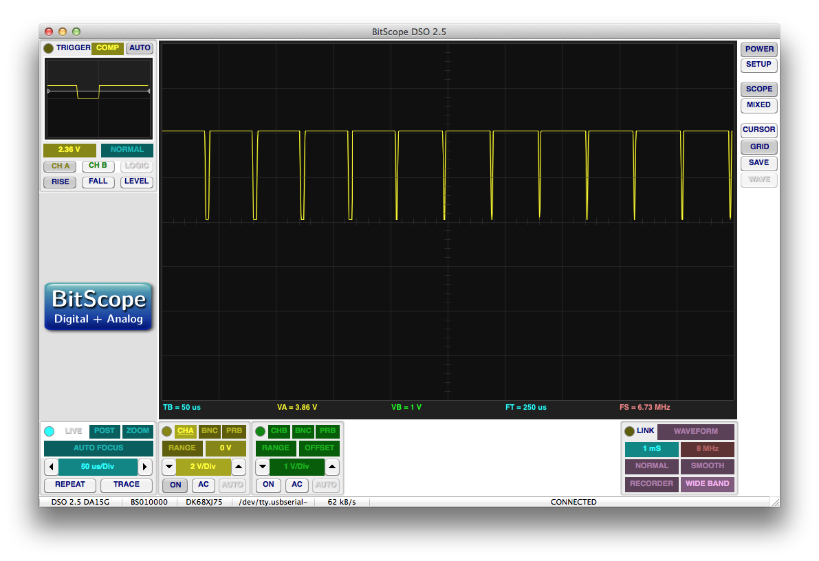
I quickly whipped out my oscilloscope and took a trace of Pin 2:
Data!
Update
While doing a similar job on a different Hit Clip (Who Let the Dogs Out by the Baha Men), I discovered different behavior. Connecting Pin 3 to ground did nothing while commenting pin 1 to ground toggled between data and no data. I'm not sure if there was a change in the Hit Clip design through generations, or if I took imprecise notes. The PCB layouts of the two clips is clearly different, and it looks like pin 3 is NC on the second clip.
I noticed an intermittent square wave with a period of almost exactly 24kHz and a duty cycle that varied with time. Pin 4 had similar data.
So there was definitely something going on here, and it was definitely digital somehow, but I needed some way to capture loads of digital data to later analyze. Fortunately, Santa gave me an 8 bit Saleae logic analyzer for Christmas:
I actually picked up the Hit Clip while looking for a good project to test this thing out. It's a really nice device, and the Windows/Mac/Linux compatible software is really slick.
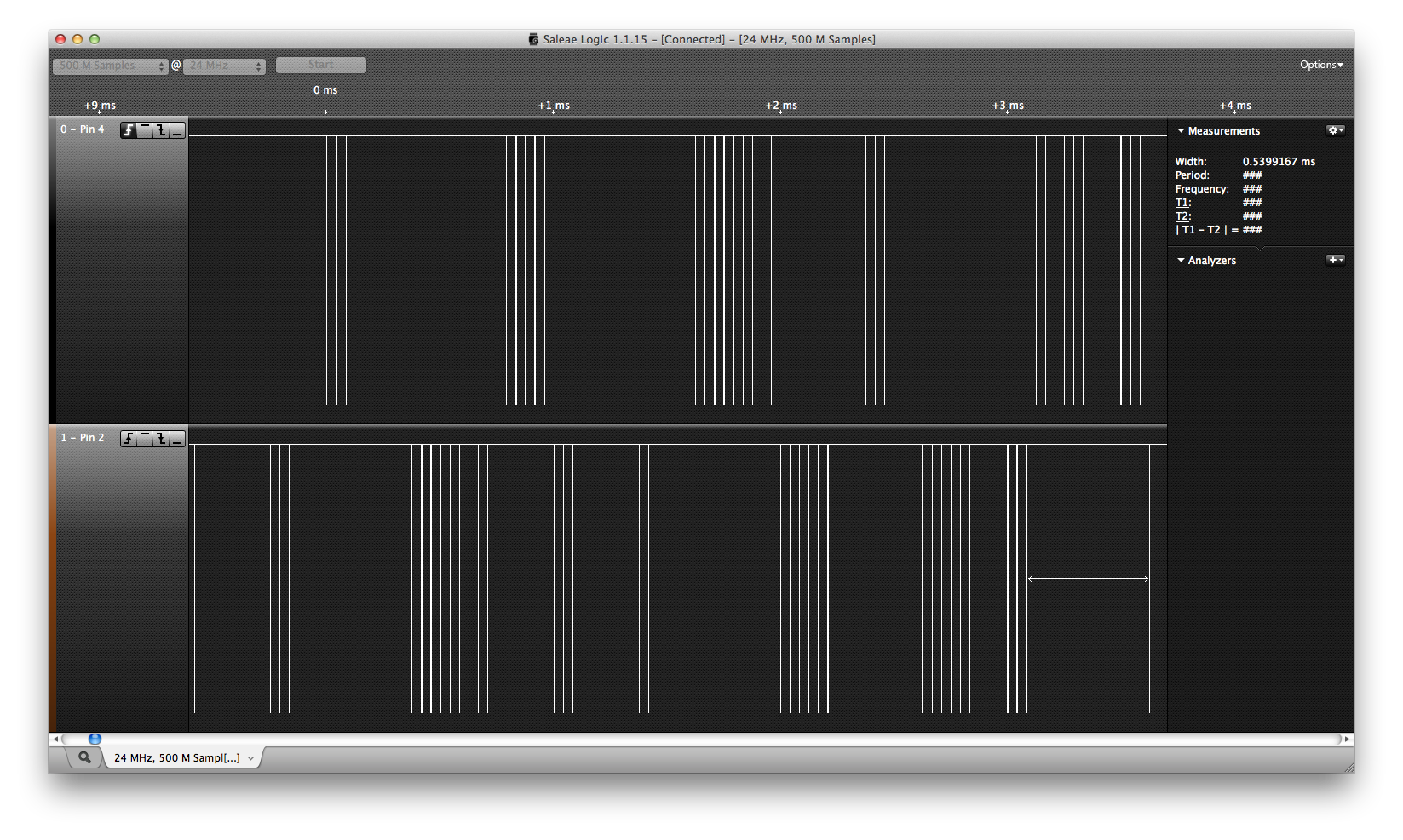
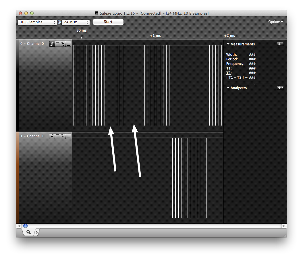
Anywho, with the Saleae connected to Pin 2 and Pin 4, I reactivated the circuit and took a trace at a 24MHz sample rate. I came up with this:
It was strange at first to see how the two data lines appeared to take turns, but once I remembered that Hit Clips only output in mono, it made a lot more sense. These two lines are encoding the same mono stream of audio.
Looking closer at the low-going blips, I noticed that they were quantized. The length of each blip was always near some integer multiple of 0.3333 s.
s.
Knowing what I know about audio amplifiers, I theorized that these two outputs are meant to directly drive the push and pull FETs of a class D amplifier in real time. In other words, a blip on one line pulls the waveform output voltage up while a blip on the other pulls it down. The width of the blip indicates how hard (or for how long) it pulls.
Update: Redditor urquan points out that this kind of modulation is called Sigma-Delta Modulation.
While it's technically a digital output, it's encoded in such a way that it can be fed directly into an analog circuit.
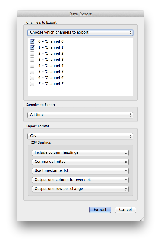
I figured that if I could give myself a stream of this data, I could probably simulate the output digitally. To cut down on the number of samples, I exported the trace to a CSV file that only records timestamps when something changes.
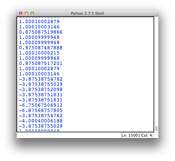
In order to make use of this data, I just needed to record how much time passed between a signal dropping low and rising up again, and I should have such data points arriving at almost exactly 24kHz. All of the data from one pin was given a positive value while the data from the other pin was given a negative value.
I also tried quantizing the data by dividing the time delays by 0.33333 s, and while this worked for small numbers, I noticed that some of the larger numbers fell pretty far from a solid integer.
It looked like 0.33333 s was a bad estimate of the actual quantization time. Thinking a little more critically, I noticed that a 24kHz wave has a period of 41.67
 s. When divided by my quantization time, this comes out to almost exactly 125 which is pretty darn close to 128, a power of two.
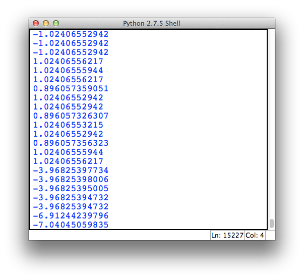
Changing my quantization time to 0.3255 s or
s or  yielded much better results:
Now the question is what to do with these numbers.
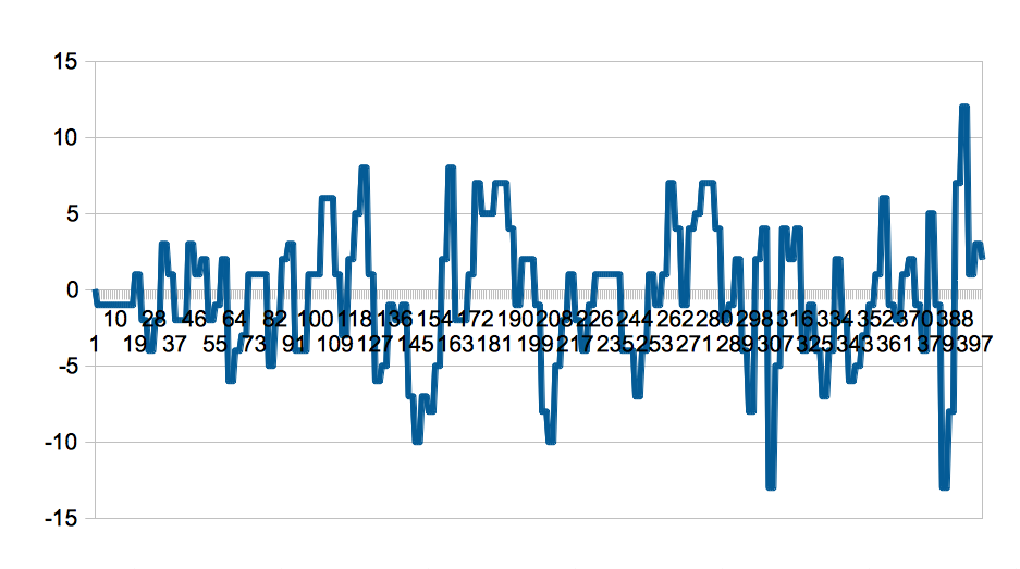
My first attempt involved just pumping them into a WAV file and taking a listen. With this setup, all of the negative numbers were negative points on the waveform. Here's the first 400 samples:
I took these values, gained them up to fill a 16 bit WAV file and took a listen:
Firstly, I was shocked to get anything even closely resembling audio. Especially something so recognizable. That being said, the audio quality isn't the best. The raw values out of the cartridge only extend from around -60 to +60 which leads me to believe that it's encoded as a 7-bit signed integer (-64 to +63). 7-bit audio isn't exactly lossless, but I wasn't convinced that this was the best I could do.
I found two problems with the way I was decoding the audio:
Empty samples
I noticed looking at the Saleae trace that there were many periods in the 24kHz digital data stream where neither trace showed a blip.
Because my script was only looking at the blips, I simply skipped passed these data points. The end result was that the music played slightly faster than it should have. This was obvious when my output WAV file was shorter than my original trace.
I modified the script to detect when more than  passed between consecutive blips and interpolate blips at the proper places by just repeating the previous value.
Push Pull simulation
I noticed later on that I wasn't really simulating the push-pull driver that the Hit Clip likely used. The digital encoding is actually more of a derivative of the output waveform rather than the waveform itself. In other words, a positive value doesn't guarantee that the output will be positive, but rather that it will have a positive slope. A larger value specifies a larger slope.
I modified my script to keep a running value starting from zero where the incoming value from the cartridge is added to the previous value to generate the next one. There was a problem of DC drift because the values don't all add up to zero. My first time through, I found that the largest value was 1 while the smallest value was somewhere around -50,000 which overflowed my signed 16 bit WAV output.
I solved this by multiplying the output value by 0.99 before storing it. This acts as a very simple high pass filter as DC offsets will slowly drop to zero over time.
The first 400 samples now looked like this:
And it sounded like this:
Looking forward
The audio is 100% recognizable which is much more than I thought I'd get out of this project. It's far from perfect, but with no base of comparison, it's possible that Hit Clips really just sounded that bad. There's also probably a large amount of filtering performed by the Hit Clip player that I would have difficulty trying to replicate. They likely mixed the tracks specifically to tailor to whichever audio stages they could make cheaply and easily, so without more information, there isn't a whole lot I can do to fix it.
The big problem with a project like this is that audio is just so easy to pull out of a circuit. Human ears are very good at picking signal out of noise, so it's difficult to tell whether or not I'm doing this right. Heck, while I was trying to get the WAV script working in Python, there were times when I had selected the wrong bit depth and produced cacophonous full scale noise, but I was still able to hear the Jackson Five playing underneath it all.
Looking at the waveform, there isn't anything totally obvious that I could be doing wrong, and yet, I can't get the audio to sound much better than the garbled samples you've heard above.
Below, I've provided a link where you can download a CSV file of the trace from my Saleae as well as my Python scripts. If you have some experience with audio processing, and have an idea for how to improve the audio output, feel free to download it and give it a try. Just make sure to report back if you figure anything out!
Update 1-2-2014
Reader Cory took up my challenge to improve the sound quality, and actually fixed it up a bunch! He method was explained in an email to me:
Technically, the Hit Clip audio is PWM, but the principles for demodulating are the same. You need nothing more than a low-pass filter. The Hit Clip devices would have contained a pair of transistors, an RC or LC filter with a cutoff frequency around 20 kHz, and a speaker. You can also use a digital low-pass filter to achieve the same result.
I have attached a script I wrote to do exactly that. It reads in the CSV data you provided, converts ch0 and ch1 into ternary (+1, 0, -1) representation, and expands it into samples at a rate of 24*128 kHz. The expanded data is decimated to 48 kHz using SciPy, which simultaneously low-pass filters the data at the Nyquist rate of 24 kHz. That data is then written out to a WAV file for your listening enjoyment. The results are surprisingly good! It definitely sounds more like what I remember it was like as a kid.
Cory's Python script can be downloaded here. And here's the result:
Sounds great!
Download the files for this project here: Hit-Clip.zip
from Hacker News https://ift.tt/3iNcicc



No comments:
Post a Comment
Note: Only a member of this blog may post a comment.