By Jonathan Smegal, M.A.Sc., and Trevor Trainor, M.A.Sc.
Control of rainwater is a primary function of the building enclosure. Water penetrating the roof, wall, and foundation can cause deterioration of the building’s structure, damage to property, and mould growth. Water on the surface or penetrating the building enclosure’s outer layers can cause corrosion and decay of sheathing and cladding attachment systems, staining and discoloration of cladding systems, and freeze-thaw damage to masonry materials.
In older buildings, surface detailing and the use of heavy stone and masonry wall assemblies have traditionally managed rainwater quite well. However, newer buildings use lightweight or hollow materials that are more sensitive to water and have less ability to remove it by drying because of increased heat and vapour control.
To offset the increased risk of moisture-related problems, a multiple step approach is recommended. Modern building enclosures should be designed to minimize the rainwater load and protect openings and penetrations by:
- controlling the flow of water on the surface of the building (i.e. deflection);
- providing a means of removing water that has leaked into the enclosure (i.e. drainage); and
- drying residual water that cannot be drained by gravity (i.e. drying).
A drip edge is a common water management detail that assists in both deflection and drainage of water from a building enclosure. However, there has been little research on the effectiveness of different drip edge designs. A recent study from Building Science Laboratories—the firm at which the authors work—addressed this gap by investigating the impact of profiles, materials, and overhang distances.
An overview of drip edge design
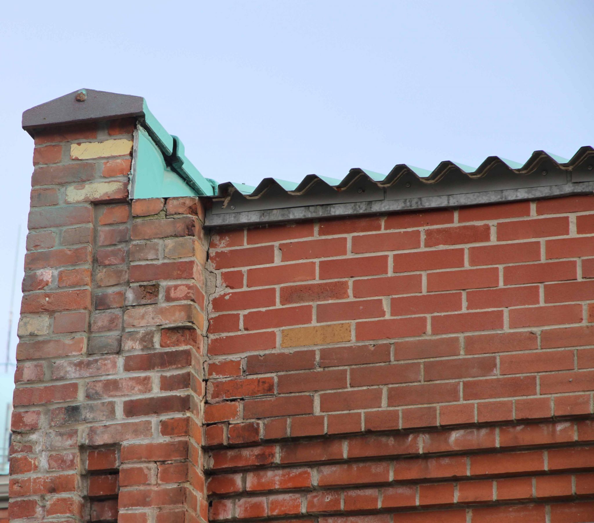
The drip edge is the leading edge of a flashing, sill, overhang, or other linear, horizontal building
element designed to shed water away from the surfaces below. Common drip edge locations include:
- windowsills;
- window head flashing;
- parapet, post, or railing cap flashing;
- through-wall flashing at masonry relieving angles; and
- edges of roofs, balconies, and other projecting building elements.
In older buildings, drip edges were often integrated with architectural details in these locations. They can be designed with several different profiles, as shown in Figure 1.


There are two primary functional requirements of the drip edge.
1. Water must be collected from surfaces above, or at a horizontal edge, and then directed outward, away from the building enclosure.
This function is particularly important at vulnerable points such as windows and mechanical penetrations, which are more susceptible to rain water penetration because of joints and exposed horizontal surfaces.
2. The water must be shed evenly along the horizontal edge to avoid concentrations of running water on surfaces below.
Localized concentrations of water can lead to discoloration, staining, and rapid deterioration of cladding materials. A commonly observed location for this type of issue is below windows—the window glazing collects and concentrates driving rain down onto the windowsill where the sill flashing drip edge drains the water onto the wall surface.
In addition to meeting water-shedding requirements, the drip edge must be strong and stiff enough to hold its shape in wind, rain, and cold weather exposure. The material must be able to resist standing water, environmental exposure (ultraviolet light [UV] and solar heat), and the physical impact that might affect a projecting surface at or near ground level.
Finally, drip edges are also significant visual objects. Therefore, they must be designed with esthetic concerns in mind. For example, the depth and projection of the profile might be chosen in part to emphasize light and shadow on the elevation.
The study design
To address the lack of information about the functional performance of different drip edge designs, a preliminary investigation was conducted examining four different metal profiles and one stone profile, with the following variables:
- hemmed or straight edge;
- 45-degree kick-out or 90-degree vertical edge;
- overhang distance of 20 and 45 mm (0.8 and 1.8 in.) from the wall surface;
- different gauges of metal; and
- various drip edge materials (i.e. metal and stone).
The vertical distribution of deposited water was measured using a custom-designed test apparatus. Horizontal distributions (i.e. patterns of drips from the edge along the length of the drip edge) were observed and described qualitatively.
Test apparatus
A 1.2-m (4-ft) wide and 1.2-m tall ‘wall’ was constructed to accept different windowsill and flashing details. Below the drip edge detail being tested, a special cladding of sheet metal was installed to allow any water deposited from the drip edge onto the ‘cladding’ to be collected and measured.
Five metal troughs of 68 mm (2 2/3 in.) in height, followed by three of 203 mm (8 in.) in height (equivalent to about one course and three courses of brickwork, respectively), were positioned directly below the windowsill. As water was deposited below the drip edge, it was caught by the troughs. The water from each trough was then directed to a collection container and the quantity was gravimetrically determined (weighed on a laboratory scale) at the end of each test.
A horizontal copper pipe with evenly spaced holes was used to supply and distribute water to the 1220-mm (48-in.) wide test section. Sealant was applied to the edges of the metal flashing to prevent lateral flow of water off the side edges. A vertical section schematic and a photo of the test setup are shown in Figure 2 and Figure 3.
Water application rate
A realistic flow rate was calculated by assuming a
3 x 1.2-m (9.8 x 3.9-ft) tall window, a rain deposition factor (RDF) of 1.0 (i.e. all the driving rain was deposited on the enclosure), and a driving rain intensity of 3 mm/h (0.1 in/h). The rain intensity was chosen based on an analysis of Toronto’s hourly climate files for the years 1965 to 1989; for this data, 94 per cent of driving rain occurs in events with an intensity of less than 3 mm/h (0.1 in/h).
Using these numbers, the rate of water application to the windowsill would be 3 x 1.2 x 0.003 m = 11 L/h (9.8 x 3.9 x 0.009 ft = 2.4 gal/h). However, during the commissioning of the testing, reliably achieving flow rates that were less than 15 L/h (3.9 gal/h) was found to be challenging, so a rate of 15 L/h (3.9 gal/h) was actually used for the study. Different building geometries, cladding types, and windowsill depths would also affect the amount of water that drained from the drip edge.
Results
The testing results are presented on the left for a 90-degree vertical drip edge (Figure 4) and 45-degree kick-out drip edge (Figure 5). The water collected in each trough is shown as a percentage of the total amount of water applied during the test. Due to the somewhat unpredictable behaviour of water flow, the test repeats show some variation. However, the trends are the same and conclusions can be made regarding drip edge effectiveness in relation to the different variables.
For each of the drip edge profiles, there were four drip edges tested:
- one at each gauge thickness (12 and 20 gauge);
- one with a hemmed edge; and
- one with an unhemmed edge.
Each drip edge was tested with an overhang of 20 and 45 mm (0.8 and 1.8 in.). For each overhang distance, there were two trials conducted to determine the repeatability (T1 and T2) at the flow rate of 15 L/h (3.9 gal/h).
Only one research study could be found that evaluated drip edge profiles based on the amount of water shed from the wall, but this study did not measure the vertical distribution of the water as it contacted the wall. Therefore, the evaluation criteria for vertical distribution for this testing was determined based on the relative results of testing.
Any trough that collected more than 10 per cent of the total water applied in one or both of the trials was coloured red with white text, to identify the relative highest collected amounts. Any drip edge tests where 90 per cent or greater of the water was shed (not collected in any of the troughs) were highlighted in green with black text. This does not mean drip edges where less water was shed would not have acceptable performance, but rather there is a greater risk of poor performance.
Ninety-degree drip edge analysis
Figure 4 shows that of all the 90-degree drip edge tests, the specific drip edges that collected the most water were 90-degree hemmed at both the 20- and 45-mm (0.8- and
1.8-in.) overhang distances. A drip edge of 12-gauge metal, with a 90-degree angle, with an unhemmed edge showed reduced wetting as compared to the same profile with a hem.
The hemmed edge deposited more water in the troughs because of the curved radius caused by bending the metal drip edge. This means water travelling down the metal flashing follows the radius toward the wall, and has enough momentum when it leaves the drip edge that it flows toward the wall instead of straight down parallel to the wall surface (Figure 6). Figure 7 shows the large radius of the thick 12-gauge metal hemmed drip edge.
The data also shows that typically a 45-mm overhang distance performed better than a 20-mm overhang distance. The only exception to this trend during testing was the 90-degree hemmed 12-gauge drip edge. It is unclear why the 45-mm overhang performed more poorly in this case.
When the thinner (20-gauge) metal drip edge was hemmed, it produced a tighter radius on the curve than the 12-gauge metal. This means on the 20-gauge drip edge less water is projected toward the cladding and the water falls more vertically than the 12-gauge hemmed metal drip edge. For the 20-gauge 90-degree drip edge, only the hemmed profile at a 20-mm overhang had a measured water collection greater than 10 per cent of the total applied.
The 90-degree hemmed at 45 mm was improved over the 20 mm in terms of distribution, but still did not shed more than 90 per cent. Both the 20-gauge 90-degree drip edges without a hem had greater than 90 per cent shedding. However, it is unlikely a 20-gauge drip edge would be specified without a hemmed edge, because the metal requires the hemmed edge for the added strength and rigidity.
Forty-five-degree drip edge analysis
The testing data for the thick 12-gauge and thin 20-gauge flashings with a 45-degree kick-out is shown in Figure 5. Compared to Figure 4, it has fewer instances where 10 per cent or greater of the total water applied was collected in a single trough. This indicates there is an overall improved vertical distribution on the surface of the wall below the drip edge. The data in Figure 5 shows all the thin 20-gauge drip edges with a 45-degree kick-out shed more than 90 per cent of the water applied in the first 1.2 m (4 ft) of collection.
In every case in Figure 5, the 45-mm (1.8-in.) overhang performed similarly or better than the 20-mm (0.8-in.) overhang of the same design. All the drip edges without a hemmed edge shed more water than the identical comparison drip edge with a hemmed edge.
The only drip edge with a 45-degree kick-out that collected more than 10 per cent of the water in a single trough was the 20-gauge hemmed edge at 20 mm (0.8 in). The water drains down the drip edge, and follows the radius toward the wall as shown in Figure 6.
Stone sill
Both vertical and horizontal distribution is necessary to avoid concentrations of rainwater. During the testing of the metal drip edges, the water tended to accumulate on the surface and drain in a few single streams (Figure 8). When a stream formed, it was consistent for the entire test. This behaviour means the water is not always well-distributed horizontally along the wall, and concentrations could form in a vertical line, even when there is good vertical distribution.
Following the tests on metal drip edges, a slightly sloped (i.e. eight-degree) stone windowsill was tested. The water flowing over the stone drip edge tended to be distributed more evenly—as drips rather than streams—over the drip edge’s length (Figure 9). The lack of individual streams means the water’s velocity was lower for the stone sill, and the distribution horizontally was more evenly distributed, minimizing the drip concentrations on the cladding. During the test of the stone windowsill drip edge, no water was collected in any troughs at the 20-mm (0.8-in.) overhang length. The stone sill was not tested at 45 mm (1.8 in.) because no water was collected at the smaller 20-mm overhang with a slight slope (i.e. eight degree).
Conclusion
The study described in this article produced several key findings related to the effectiveness of different drip edge materials, profiles and overhang distances:
- Whether or not the edge of the drip edge was hemmed had the greatest impact on the shedding of water from the surface of the wall. This impact was greater for the thick 12-gauge drip edge than for the thinner 20-gauge drip edge.
- The larger 45-mm (1.8-in.) overhang had greater measured water-shedding capability when compared to the 20-mm (0.8-in.) overhang, in every test but one.
- Adding a 45-degree kick-out also increased the percentage of water shed from the apparatus compared to the 90-degree vertical drip edge.
- The thinner 20-gauge drip edge generally had improved vertical distribution compared to the 12 gauge, but 20 gauge is thin enough it would require a hemmed edge to provide strength and rigidity to the drip edge profile on a building.
- There was no water collected in any of the troughs during the test of the stone sill with a small (i.e. eight degree) slope at 20-mm (0.8-in.) overhang distance. The water was better distributed horizontally compared to the metal drip edges.
One practical conclusion is better drip edge performance can be achieved by increasing the thickness of the metal drip edge so it does not require a hemmed edge. For example, it would be better to use 12 gauge without a hemmed edge, compared to a 20 gauge with a hemmed edge, especially when the overhang distance is small.
 Jonathan Smegal, M.A.Sc., is a senior associate with Building Science Consulting Inc. (BSCI), a consulting firm specializing in design facilitation, building enclosure commissioning, forensic investigation, and training and communications. Its research division, Building Science Laboratories (BSL), provides a range of R&D services. His work for BSCI includes laboratory research, hygrothermal modeling, field monitoring of wall performance, and forensic analysis of building failures. Smegal’s research has included cladding deflection tests, drainage balance testing, and specialized water uptake and vapour permeance testing. He can be reached via e-mail at jsmegal@buildingsciencelabs.com.
 Trevor Trainor, M.A.S.c., is an associate at BSCI/BSL. A recent graduate of the University of Waterloo’s Building Science program, his research involved modelling wood-framed building envelope systems for net-zero housing and field exposure testing of high-R wall designs. Trainor can be contacted at trevor@buildingsciencelabs.com.
Control the content you see on ConstructionCanada.net!
Learn More.from Hacker News https://ift.tt/5zDAXRK
No comments:
Post a Comment
Note: Only a member of this blog may post a comment.