In this post, I create a floppy controller for my raspberry pi model 4 B.
Purpose
If there’s one criticism I hear more often than any other about the pi, it’s “I wish my Raspberry Pi had a floppy drive“. It’s really shocking that the pi doesn’t have the ubiquitous 34-pin floppy header that we all know and love. How else are you supposed to interface your Tandon TM100-2A or your Teac FD-55BR or even, for you cutting edge folks, your Sony MFP290 3.5” high density drive?
So I set along to create this much needed had, the missing link between the raspberry pi and the floppy disk drive.
Design
I’ve used the WD37C65 floppy controller IC a few times in the past, most notably as part of a floppy interface project for the RC2014 computer. I’ve previously played with the RomWBW CP/M distribution for the RC2014, and the floppy drive that’s contained as part of it. So I knew this chip reasonably well and decided to go ahead and make use of it for my raspberry pi project.
The WD37C65 is a great single-chip solution, combining the floppy controller, data separator, and control latch. It actually has three different chip selects, one for the controller, one for the DOR (disk operation register?) and one for the DCR (disk configuration register?). You can easily interface it with a plethora of vintage drives, everything from your basic 360KB floppy drive to your 1.44 MB high density drive. Yes, I’m pretty sure when working on the RC2014 I interface it to some old 8″ qume drives as well. There are several selectable data rates, and you can program the number of tracks, number of heads, number of sectors, and bytes per sector. The controller can be used with an interrupt or it can use polling. It’s a great vintage IC to use.
Here’s my schematic for the raspberry pi floppy controller hat:
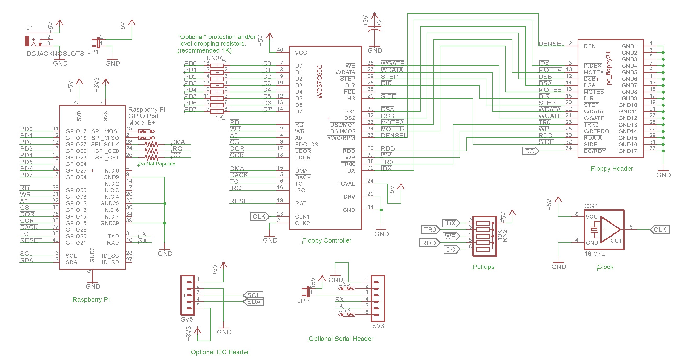
The circuit is really pretty simple, there’s only one IC, the WD37C65 controller. This IC connects directly to the 34-pin floppy header. There are also some pullups associated with about a half-dozen of the floppy drive status lines, things like the index sensor and the write protect sensor. There’s a 16 MHz oscillator that supplies the clock that the controller needs.
Most of the controller lines are interfaced directly to the pi. Lines like RD, WR, CS, A0, etc., are strictly pi-to-controller signals and both the pi and the controller are compatible even though the pi is a 3.3V device and the controller is a 5V device.
The data bus, D0-D7 is a bit more controversial. The signal levels are compatible when the pi is writing to the controller (3.3V -> 5V), but are not necessarily compatible when the controller is writing data to the pi (5V – 3.3V). When doing that sort of thing on a hobbyist-grade device I’ll often throw in some current limiting resistors. That’s the purpose of the resistor network RN3. In my video I did actually test it wired straight across, and damaged neither the pi nor the controller, though it may be risky to do so. As far as I’m aware, there isn’t a great deal of real-world studies on interfacing a pi with 5V devices, other than a lot of people saying “don’t do it”. For the next revision of this board, I’ll probably switch to using a proper level converter IC and eliminate the controversy.
I put two additional headers on the board, one for I2C and the other for serial. These fit some use cases I have planned for the board.
Implementation
Below is a picture of the completed hat:
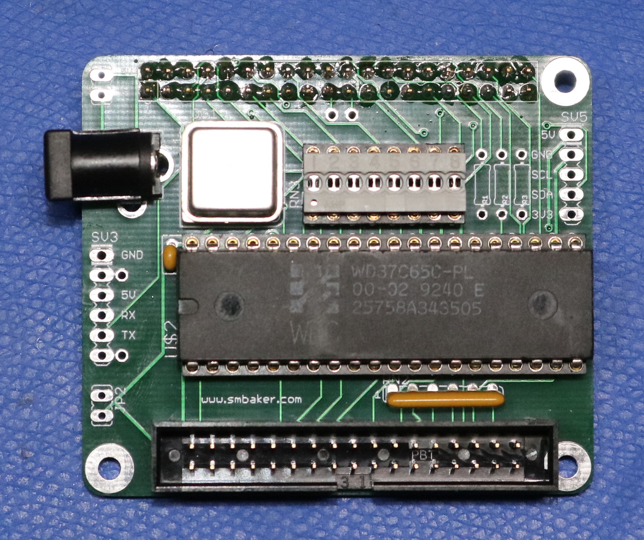
As you can see, a pretty simple one-chip hat. The 16-pin grey thing is a shunt. This is the configuration I used in the video. As I mentioned in the design section, perhaps safer here to use a DIP resistor network (isolated, not bussed) or solder in discrete resistors due to the level difference between the pi and controller IC.
The floppy header is at the bottom. If you get the shrouded header like I did, with the little cutout in the middle, it’ll keep you from pulling in your floppy cable backwards.
The stacking header for the pi protrudes out the back.
The barrel jack is optional and would allow you to supply 5VDC from a barrel jack instead of the pi’s USB-C header, if you’re a barrel jack sort of person. If you’re one of those modern USB-C people, then just use the USB-C.
Software
I wrote a user-mode driver in python, with C extensions for some of the IO functions. This presents a couple challenges:
- Raspbian is not a real-time OS. There’s no guarantee that your user-mode process will not be interrupted.
- When transferring data (i.e. read sector or write sector), the floppy controller wants every byte transferred within 13ms (standard density) or 26ms (high density). If you don’t transfer the byte in time, the controller have no place to put the next byte — the disk is spinning! — and will declare an overrun.
These two together mean that a user-mode floppy driver may have occasional overruns. No problem, when we get an overrun, we can just retry. It does have an adverse affect on performance though, and the problem is much worse when reading high density disks than when reading low density disks.
Some techniques at https://www.raspberrypi.org/forums/viewtopic.php?t=228727 can be used to mitigate the problem. By dedicating a core to the floppy driver you lose a core from general purpose use, but you also reduce the odds of Linux interrupting the floppy driver at an inopportune time. An interrupt may still occur, but less often and with less adverse affect than when sharing a core with other processes.
The ultimate solution would be to write a kernel driver. I’ve written kernel modules in the past. Perhaps it’s something I will do again, but I have no immediate plans to do so.
Demo Script
Here is a list of commands I performed in my short demo in the video:
# format the diskette
sudo python ./fdtool.py --media 360 format

# write a DOS 3.10 image to the disk
cat dos310_1.img | sudo python ./fdtool.py --realtime --pincpu 3 --media 360 --disk write

# Read the first sector and display it in the terminal
sudo python ./fdtool.py --realtime --pincpu 3 --media 360 read | hexdump -C

# Read the entire disk and display it in the terminal
sudo python ./fdtool.py --realtime --pincpu 3 --media 360 --disk read | hexdump -C
Note that the sudo goes along with the --realtime --pincpu 3 arguments and handles pinning the floppy controller to cpu core #3. It’s also necessary to add isolcpus=3 to your /boot/cmdline.txt. It will work without the sudo and without the pinning arguments, but you’ll get more interruptions and more retries needed.
Resources
Acknowledgements
- The RomWBW CP/M assembly floppy driver, fd.asm, served as a basis for much of my learning how to program the WD37C65 and a basis for writing my python driver.
- https://www.raspberrypi.org/forums/viewtopic.php?t=228727 contains useful information on real-time scheduling on the pi that was helpful in improving performance and reducing the retry count.
from Hacker News https://ift.tt/3uexFst
No comments:
Post a Comment
Note: Only a member of this blog may post a comment.