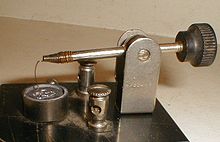
Galena cat whisker detector used in early crystal radio
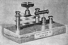
Precision crystal detector with
iron pyrite
crystal, used in commercial wireless stations, 1914. The crystal is inside the metal capsule under the vertical needle
(right)
. The leaf springs and thumbscrew allow fine adjustment of the pressure of the needle on the crystal.
A crystal detector is an obsolete electronic component used in some early 20th century radio receivers that consists of a piece of crystalline mineral which rectifies the alternating current radio signal.[1] It was employed as a detector (demodulator) to extract the audio modulation signal from the modulated carrier, to produce the sound in the earphones.[2][3] It was the first type of semiconductor diode,[2][4] and one of the first semiconductor electronic devices.[5] The most common type was the so-called cat whisker detector, which consisted of a piece of crystalline mineral, usually galena (lead sulfide), with a fine wire touching its surface.[1][5][6]
The "asymmetric conduction" of electric current across electrical contacts between a crystal and a metal was discovered in 1874 by Karl Ferdinand Braun.[7] Crystals were first used as radio wave detectors in 1894 by Jagadish Chandra Bose in his microwave experiments.[2][8][9] Bose first patented a crystal detector in 1901.[10] The crystal detector was developed into a practical radio component mainly by G. W. Pickard,[5][11][12] who began research on detector materials in 1902 and found hundreds of substances that could be used in forming rectifying junctions.[3][13] The physical principles by which they worked were not understood at the time they were used,[14] but subsequent research into these primitive point contact semiconductor junctions in the 1930s and 1940s led to the development of modern semiconductor electronics.[1][5][15][16]
The unamplified radio receivers that used crystal detectors were called crystal radios.[17] The crystal radio was the first type of radio receiver that was used by the general public,[15] and became the most widely used type of radio until the 1920s.[18] It became obsolete with the development of vacuum tube receivers around 1920,[1][15] but continued to be used until World War II and remains a common educational project today thanks to its simple design.
How it works[edit]
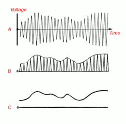
Diagram showing how a crystal detector works
The contact between two dissimilar materials at the surface of the detector's semiconducting crystal forms a crude semiconductor diode, which acts as a rectifier, conducting electric current well in only one direction and resisting current flowing in the other direction.[3] In a crystal radio, it was connected between the tuned circuit, which passed on the oscillating current induced in the antenna from the desired radio station, and the earphone. Its function was to act as a demodulator, rectifying the radio signal, converting it from alternating current to a pulsing direct current, to extract the audio signal (modulation) from the radio frequency carrier wave.[3][5] An AM demodulator which works in this way, by rectifying the modulated carrier, is called an envelope detector. The audio frequency current produced by the detector passed through the earphone causing the earphone's diaphragm to vibrate, pushing on the air to create sound waves. The earphone was typically a piezoelectric crystal type, so sensitive that the radio receiver could operate without an electrical power supply, using only energy from the incident radio wave to drive the earphone directly, with no electronic amplification. This diagram shows a simplified explanation of how it works:[7][19][20]
- (A) This graph shows the amplitude modulated radio signal from the receiver's tuned circuit, which is applied as a voltage across the detector's contacts. The rapid oscillations are the radio frequency carrier wave. The audio signal (the sound) is contained in the slow variations (modulation) of the size of the waves. If this signal were applied directly to the earphone, it could not be converted to sound, because the audio excursions are the same on both sides of the axis, averaging out to zero, which would result in no net motion of the earphone's diaphragm.
- (B) This graph shows the current through the crystal detector which is applied to the earphone and bypass capacitor. The crystal conducts current in only one direction, stripping off the oscillations on one side of the signal, leaving a pulsing direct current whose amplitude does not average zero but varies with the audio signal.
- (C) This graph shows the current which passes through the earphone. A bypass capacitor across the earphone terminals, in combination with the intrinsic forward resistance of the diode, creates a low-pass filter that smooths the waveform by removing the radio frequency carrier pulses and leaving the audio signal. When this varying current passes through the earphone piezoelectric crystal, it causes the crystal to deform (flex), deflecting the earphone diaphragm; the varying deflections of the diaphragm cause it to vibrate and produce sound waves (acoustic waves). If instead a voice-coil type headphone is used, the varying current from the low-pass filter flows through the voice coil, generating a varying magnetic field which pulls and pushes the earphone diaphragm, again causing it to vibrate and produce sound.
Circuit of a simple crystal radio. The crystal detector D is connected between the tuned circuit L,C1 and the earphone E. C2 is the bypass capacitor.
Pictorial diagram from 1922 showing the circuit of a cat whisker crystal radio. This common circuit did not use a tuning
capacitor
, but used the capacitance of the antenna to form the
tuned circuit
with the coil.
Crystal radios had no amplifying components to increase the loudness of the radio signal; the sound power produced by the earphone came solely from the radio waves of the radio station being received, intercepted by the antenna. Therefore, the sensitivity of the detector was a major factor determining the sensitivity and reception range of the receiver, motivating much research into finding sensitive detectors.
In addition to its main use in crystal radios, crystal detectors were also used as radio wave detectors in scientific experiments, in which the DC output current of the detector was registered by a sensitive galvanometer, and in test instruments such as wavemeters used to calibrate the frequency of radio transmitters.[21]
The crystal detector consisted of an electrical contact between the surface of a semiconducting crystalline mineral and either a metal or another crystal.[3][5] Since at the time they were developed no one knew how they worked, crystal detectors evolved by trial and error. The construction of the detector depended on the type of crystal used, as it was found different minerals varied in how much contact area and pressure on the crystal surface was needed to make a sensitive rectifying contact.[3][22] Crystals that required a light pressure like galena were used with the wire cat whisker contact; silicon was used with a heavier point contact, while silicon carbide (carborundum) could tolerate the heaviest pressure.[3][22][23] Another type used two crystals of different minerals with their surfaces touching, the most common being the "Perikon" detector. Since the detector would only function when the contact was made at certain spots on the crystal surface, the contact point was almost always made adjustable. Below are the major categories of crystal detectors used during the early 20th century:
Cat whisker detector[edit]
Galena cat whisker detector from a 1920s crystal radio
Cat whisker detector using iron pyrite crystal
Galena detector in a cheap 1930s crystal radio
Popular form in portable radios, with the crystal protected inside a glass tube
Patented by Karl Ferdinand Braun[2] and Greenleaf Whittier Pickard[6] in 1906, this was the most common type of crystal detector, mainly used with galena[24][25] but also other crystals. It consisted of a pea-size piece of crystalline mineral in a metal holder, with its surface touched by a fine metal wire or needle (the "cat whisker").[3][5][23][26] The contact between the tip of the wire and the surface of the crystal formed a crude unstable point-contact metal–semiconductor junction, forming a Schottky barrier diode.[5][27] The wire whisker is the anode, and the crystal is the cathode; current can flow from the wire into the crystal but not in the other direction.
Only certain sites on the crystal surface functioned as rectifying junctions.[5][22] The device was very sensitive to the exact geometry and pressure of contact between wire and crystal, and the contact could be disrupted by the slightest vibration.[5][7][14] Therefore, a usable point of contact had to be found by trial and error before each use.[5] The wire was suspended from a moveable arm and was dragged across the crystal face by the user until the device began functioning.[22] In a crystal radio, the user would tune the radio to a strong local station if possible and then adjust the cat whisker until the station or radio noise (a static hissing noise) was heard in the radio's earphones.[28] This required some skill and a lot of patience.[7] An alternative method of adjustment was to use a battery-operated buzzer connected to the radio's ground wire or inductively coupled to the tuning coil, to generate a test signal.[28][29] The spark produced by the buzzer's contacts functioned as a weak radio transmitter whose radio waves could be received by the detector, so when a rectifying spot had been found on the crystal the buzz could be heard in the earphones, at which time the buzzer was turned off.
The detector consisted of two parts mounted next to each other on a flat nonconductive base:
- Crystal

Galena crystals sold for use in crystal detectors, Poland, 1930s
- A crystalline mineral formed the semiconductor side of the junction. The most common crystal used was galena (lead sulfide, PbS, varieties were sold under the names "Lenzite"[22] and "Hertzite"),[5][24][25] a widely occurring ore of lead, although other crystalline minerals were also used, the more common ones were iron pyrite (iron sulfide, FeS2, "fool's gold", also sold under the trade names "Pyron"[30] and "Ferron"[22]),[3][24][26]molybdenite (molybdenum disulfide, MoS2),[22][24][26] and cerussite (lead carbonate, PbCO3)[24] Not all specimens of a crystal would function in a detector, often several crystal pieces had to be tried to find an active one.[22] Galena with good detecting properties was rare and had no reliable visual characteristics distinguishing it from galena samples with poor detecting properties. A rough pebble of detecting mineral about the size of a pea was mounted in a metal cup, which formed one side of the circuit. The electrical contact between the cup and the crystal had to be good, because this contact must not act as a second rectifying junction, creating two back-to-back diodes which would prevent the device from conducting at all.[31] To make good contact with the crystal, it was either clamped with setscrews or embedded in solder. Because the relatively high melting temperature of tin-lead solder can damage many crystals, a fusible alloy with a low melting point, well under 200 °F (93 °C), such as Wood's metal was used.[5][22][24] One surface was left exposed to allow contact with the cat-whisker wire.
- Cat whisker
- The "cat whisker", a springy piece of thin metal wire, formed the metal side of the junction. Phosphor bronze wire of about 30 AWG / 0.25 mm diameter was commonly used because it had the right amount of springiness.[28][30][32] It was mounted on an adjustable arm with an insulated handle so that the entire exposed surface of the crystal could be probed from many directions to find the most sensitive spot. Cat whiskers in homemade detectors usually had a simple curved shape, but most professional cat whiskers had a coiled section in the middle that served as a spring.[33] The crystal required just the right gentle pressure by the wire; too much pressure caused the device to conduct in both directions.[5] Precision detectors made for radiotelegraphy stations often used a metal needle instead of a "cat's whisker", mounted on a thumbscrew-operated leaf spring to adjust the pressure applied. Gold or silver needles were used with some crystals.
Carborundum detector[edit]
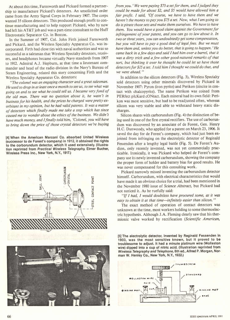
Professional carborundum detector used in radiotelegraphy stations
Carborundum detector marketed to radio hobbyists, 1911
Invented in 1906 by Henry H. C. Dunwoody,[34][35] this consisted of a piece of silicon carbide (SiC, then known by the trade name carborundum), either clamped between two flat metal contacts,[5][22][26] or mounted in fusible alloy in a metal cup with a contact consisting of a hardened steel point pressed firmly against it with a spring.[36] Carborundum, an artificial product of electric furnaces produced in 1893, required a heavier pressure than the cat whisker contact.[3][5][22][36] The carborundum detector was popular[24][36] because its sturdy contact did not require readjustment each time it was used, like the delicate cat whisker devices.[3][22][26] Some carborundum detectors were adjusted at the factory and then sealed and did not require adjustment by the user.[3] It was not sensitive to vibration and so was used in shipboard wireless stations where the ship was rocked by waves, and military stations where vibration from gunfire could be expected.[5][22] Another advantage was that it was tolerant of high currents, and could not be "burned out" by atmospheric electricity from the antenna.[3] Therefore, it was the most common type used in commercial radiotelegraphy stations.[36]
Silicon carbide is a semiconductor with a wide band gap of 3 eV, so to make the detector more sensitive a forward bias voltage of several volts was usually applied across the junction by a battery and potentiometer.[22][26][36][35] The voltage was adjusted with the potentiometer until the sound was loudest in the earphone. The bias moved the operating point to the curved "knee" of the device's current–voltage curve, which produced the largest rectified current.[22]
Original Pickard silicon detector 1906
Silicon-antimony detector used in naval wireless stations 1919. The silicon crystal is mounted on an adjustable stage that can be moved in two dimensions by micrometer knobs (right) to find sensitive spot.
Silicon detector[edit]
Patented and first manufactured in 1906 by Pickard,[11][35] this was the first type of crystal detector to be commercially produced.[12] Silicon required more pressure than the cat whisker contact, although not as much as carborundum.[22] A flat piece of silicon was embedded in fusible alloy in a metal cup, and a metal point, usually brass or gold, was pressed against it with a spring.[26][37] The surface of the silicon was usually ground flat and polished. Silicon was also used with antimony[22] and arsenic[30] contacts. The silicon detector was popular because it had much the same advantages as carborundum; its firm contact could not be jarred loose by vibration, but it did not require a bias battery, so it saw wide use in commercial and military radiotelegraphy stations.[22]
Crystal-to-crystal detectors[edit]
(left) "Perikon" zincite-chalcopyrite detector, ca. 1912, manufactured by Pickard's firm, Wireless Specialty Apparatus Co. (right) Another form of crystal-to-crystal contact detector, made as a sealed plugin unit, ca. 1919
Another category was detectors which used two different crystals with their surfaces touching, forming a crystal-to-crystal contact.[5][26] The "Perikon" detector, invented 1908 by Pickard[38] was the most common. Perikon stood for "PERfect pIcKard cONtact".[5] It consisted of two crystals in metal holders, mounted face to face. One crystal was zincite (zinc oxide, ZnO), the other was a copper iron sulfide, either bornite (Cu5FeS4) or chalcopyrite (CuFeS2).[22][26] In Pickard's commercial detector (see picture), multiple zincite crystals were mounted in a fusible alloy in a round cup (on right), while the chalcopyrite crystal was mounted in a cup on an adjustable arm facing it (on left). The chalcopyrite crystal was moved forward until it touched the surface of one of the zincite crystals. When a sensitive spot was located, the arm was locked in place with the setscrew. Multiple zincite pieces were provided because the fragile zincite crystal could be damaged by excessive currents and tended to "burn out" due to atmospheric electricity from the wire antenna or currents leaking into the receiver from the powerful spark transmitters used at the time. This detector was also sometimes used with a small forward bias voltage of around 0.2V from a battery to make it more sensitive.[22][36]
Although the zincite-chalcopyrite "Perikon" was the most widely used crystal-to-crystal detector, other crystal pairs were also used. Zincite was used with carbon, galena, and tellurium. Silicon was used with arsenic,[30]antimony[22] and tellurium crystals.
History[edit]

The graphic symbol used for solid-state diodes originated as a drawing of a point contact crystal detector.
[39][original research?]
During the first three decades of radio, from 1888 to 1918, called the wireless telegraphy or "spark" era, primitive radio transmitters called spark gap transmitters were used, which generated radio waves by an electric spark.[17][40] These transmitters were unable to produce the continuous sinusoidal waves which are used to transmit audio (sound) in modern AM or FM radio transmission.[41] Instead spark gap transmitters transmitted information by wireless telegraphy; the user turned the transmitter on and off rapidly by tapping on a telegraph key, producing pulses of radio waves which spelled out text messages in Morse code. Therefore, the radio receivers of this era did not have to demodulate the radio wave, extract an audio signal from it as modern receivers do, they merely had to detect the presence or absence of the radio waves, to make a sound in the earphone when the radio wave was present to represent the "dots" and "dashes" of Morse code.[1] The device which did this was called a detector. The crystal detector was the most successful of many detector devices invented during this era.
The crystal detector evolved from an earlier device,[42] the first primitive radio wave detector, called a coherer, developed in 1890 by Édouard Branly and used in the first radio receivers in 1894–96 by Marconi and Oliver Lodge.[5][40] Made in many forms, the coherer consisted of a high resistance electrical contact, composed of conductors touching with a thin resistive surface film, usually oxidation, between them.[40] Radio waves changed the resistance of the contact, causing it to conduct a DC current. The most common form consisted of a glass tube with electrodes at each end, containing loose metal filings in contact with the electrodes.[1][5] Before a radio wave was applied, this device had a high electrical resistance, in the megohm range. When a radio wave from the antenna was applied across the electrodes it caused the filings to "cohere" or clump together and the coherer's resistance fell, causing a DC current from a battery to pass through it, which rang a bell or produced a mark on a paper tape representing the "dots" and "dashes" of Morse code. Most coherers had to be tapped mechanically between each pulse of radio waves to return them to a nonconductive state.[17][40]
The coherer was a very poor detector, motivating much research to find better detectors.[5] It worked by complicated thin film surface effects, so scientists of the time didn't understand how it worked, except for a vague idea that radio wave detection depended on some mysterious property of "imperfect" electrical contacts.[5] Researchers investigating the effect of radio waves on various types of "imperfect" contacts to develop better coherers, invented crystal detectors.[42]
Braun's experiments[edit]
The "unilateral conduction" of crystals was discovered by Karl Ferdinand Braun, a German physicist, in 1874 at the University of Würzburg.[2][8][43] He studied copper pyrite (Cu5FeS4), iron pyrite (iron sulfide, FeS2), galena (PbS) and copper antimony sulfide (Cu3SbS4).[44] This was before radio waves had been discovered, and Braun did not apply these devices practically but was interested in the nonlinear current–voltage characteristic that these sulfides exhibited. Graphing the current as a function of voltage across a contact made by a piece of mineral touched by a wire cat whisker, he found the result was a line that was flat for current in one direction but curved upward for current in the other direction, instead of a straight line, showing that these substances did not obey Ohm's law. Due to this characteristic, some crystals had up to twice as much resistance to current in one direction as they did to current in the other. In 1877 and 1878 he reported further experiments with psilomelane, (Ba,H
2O)
2Mn
5O
10. Braun did investigations which ruled out several possible causes of asymmetric conduction, such as electrolytic action and some types of thermoelectric effects.[44]
Thirty years after these discoveries, after Bose's experiments, Braun began experimenting with his crystalline contacts as radio wave detectors.[2] In 1906 he obtained a German patent on a galena cat whisker detector, but was too late to obtain patents in other countries.
Bose's experiments[edit]
Bose's galena detector from his 1901 patent. This version was deliberately made to look and function like a human eyeball, with a lens focusing millimeter waves on the galena contact.
Bose's millimeter wave spectrometer, 1897. The galena detector is inside the horn antenna (F). The battery (V) creates a current through the detector measured by the galvanometer (G)
The first person to use crystals for radio wave detection was Indian physicist Jagadish Chandra Bose of the University of Calcutta in his landmark 60 GHz microwave optics experiments from 1894 to 1900.[45][46] Like other scientists since Hertz, Bose was investigating the similarity between radio waves and light by duplicating classic optics experiments with radio waves.[47] He first used a coherer consisting of a steel spring pressing against a metal surface with a current passing through it. Dissatisfied with this detector, around 1897 Bose measured the change in resistivity of dozens of metals and metal compounds exposed to microwaves.[46][48] He experimented with many substances as contact detectors, focusing on galena.
His detectors consisted of a small galena crystal with a metal point contact pressed against it with a thumbscrew, mounted inside a closed waveguide ending in a horn antenna to collect the microwaves.[46] Bose passed a current from a battery through the crystal, and used a galvanometer to measure it. When microwaves struck the crystal the galvanometer registered a drop in resistance of the detector. At the time scientists thought that radio wave detectors functioned by some mechanism analogous to the way the eye detected light, and Bose found his detector was also sensitive to visible light and ultraviolet, leading him to call it an artificial retina. He patented the detector 30 September 1901.[8][10] This is often considered the first patent on a semiconductor device.
Pickard: first commercial detectors[edit]
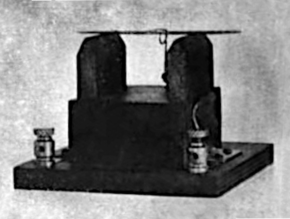
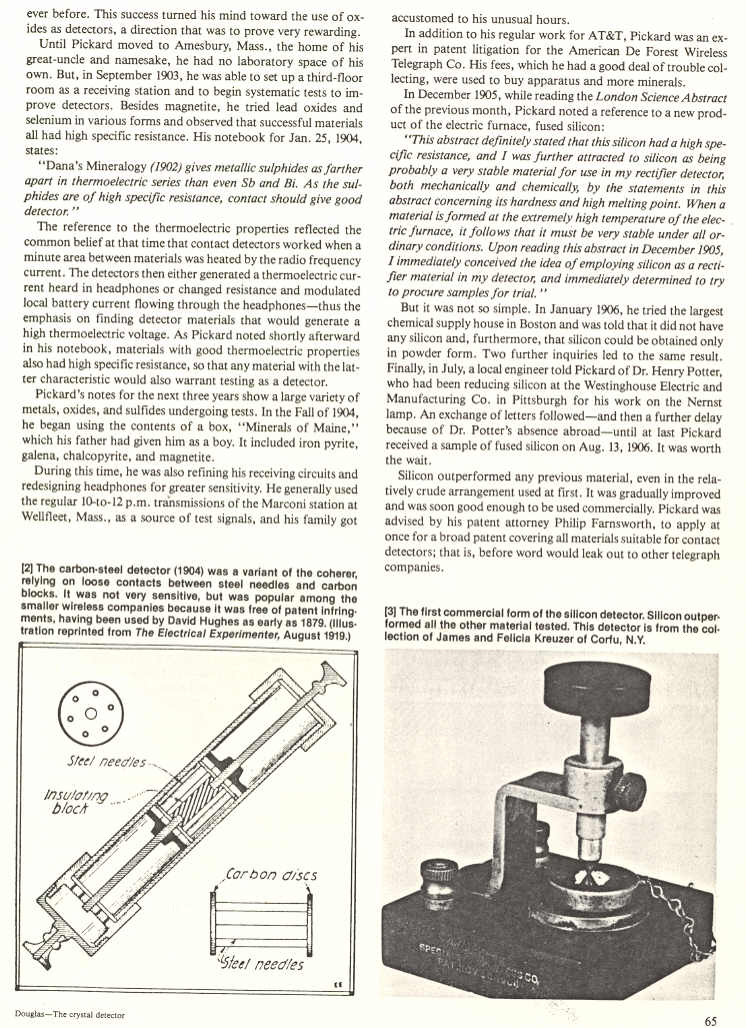
"Microphone" coherer detector from 1909 similar to one Pickard discovered rectification with, widely used in the first receivers. It consists of a steel needle resting on two carbon blocks. A semiconducting layer of corrosion on the steel may have been responsible for the rectification.
Greenleaf Whittier Pickard may be the person most responsible for making the crystal detector a practical device. Pickard, an engineer with the American Wireless Telephone and Telegraph Co. invented the rectifying contact detector,[49][50] discovering rectification of radio waves in 1902 while experimenting with a coherer detector consisting of a steel needle resting across two carbon blocks.[12][13][50] On 29 May 1902 he was operating this device, listening to a radiotelegraphy station. Coherers required an external current source to operate, so he had the coherer and telephone earphone connected in series with a 3 cell battery to provide power to operate the earphone. Annoyed by background "frying" noise caused by the current through the carbon, he reached over to cut two of the battery cells out of the circuit to reduce the current[12][13]
The frying ceased, and the signals, though much weakened, became materially clearer through being freed of their background of microphonic noise. Glancing over at my circuit, I discovered to my great surprise that instead of cutting out two of the cells I had cut out all three; so, therefore, the telephone diaphragm was being operated solely by the energy of the receiver signals. A contact detector operating without local battery seemed so contrary to all my previous experience that ... I resolved at once to thoroughly investigate the phenomenon.[12][13]
The generation of an audio signal without a DC bias battery made Pickard realize the device was acting as a rectifier. During the next four years, Pickard conducted an exhaustive search to find which substances formed the most sensitive detecting contacts, eventually testing thousands of minerals,[8] and discovered about 250 rectifying crystals.[5][12][13] In 1906 he obtained a sample of fused silicon, an artificial product recently synthesized in electric furnaces, and it outperformed all other substances.[12][13] He patented the silicon detector 30 August 1906.[8][11] In 1907 he formed a company to manufacture his detectors, Wireless Specialty Products Co., and the silicon detector was the first crystal detector to be sold commercially.[12] Pickard went on to produce other detectors using the crystals he had discovered; the more popular being the iron pyrite "Pyron" detector and the zincite–chalcopyrite crystal-to-crystal "Perikon" detector in 1908,[38] which stood for "PERfect pIcKard cONtact".[5]
Use during the wireless telegraphy era[edit]

Marconi Type 106 crystal receiver made from 1915 to around 1920. Detector is visible at lower right. Until the triode began to replace it in World War I the crystal detector was cutting-edge technology.
Guglielmo Marconi developed the first practical wireless telegraphy transmitters and receivers in 1896, and radio began to be used for communication around 1899. The coherer was used as detector for the first 10 years, until around 1906.[18] During the wireless telegraphy era prior to 1920, there was virtually no broadcasting; radio served as a point-to-point text messaging service. Until the triode vacuum tube began to be used around World War I, radio receivers had no amplification and were powered only by the radio waves picked up by their antennae.[12] Long distance radio communication depended on high power transmitters (up to 1 MW), huge wire antennas, and a receiver with a sensitive detector.[12]
Crystal detectors were invented by several researchers at about the same time.[5] Braun began to experiment with crystal detectors around 1899,[2] around when Bose patented his galena detector.[8] Pickard invented his silicon detector in 1906. Also in 1906 Henry Harrison Chase Dunwoody,[51] a retired general in the U.S. Army Signal Corps, patented the silicon carbide (carborundum) detector,[34][35] Braun patented a galena cat whisker detector in Germany,[52] and L. W. Austin invented a silicon–tellurium detector.
Around 1907 crystal detectors replaced the coherer and electrolytic detector to become the most widely used form of radio detector.[18][53] Until the triode vacuum tube began to be used during World War I, crystals were the best radio reception technology, used in sophisticated receivers in wireless telegraphy stations, as well as in homemade crystal radios.[54] In transoceanic radiotelegraphy stations elaborate inductively coupled crystal receivers fed by mile long wire antennas were used to receive transatlantic telegram traffic.[55] Much research went into finding better detectors and many types of crystals were tried.[31] The goal of researchers was to find rectifying crystals that were less fragile and sensitive to vibration than galena and pyrite. Another desired property was tolerance of high currents; many crystals would become insensitive when subjected to discharges of atmospheric electricity from the outdoor wire antenna, or current from the powerful spark transmitter leaking into the receiver. Carborundum proved to be the best of these;[36] it could rectify when clamped firmly between flat contacts. Therefore, carborundum detectors were used in shipboard wireless stations where waves caused the floor to rock, and military stations where gunfire was expected.[5][22]
In 1907–1909, George Washington Pierce at Harvard conducted research into how crystal detectors worked.[12][44] Using an oscilloscope made with Braun's new cathode ray tube, he produced the first pictures of the waveforms in a working detector, proving that it did rectify the radio wave. During this era, before modern solid-state physics, most scientists believed that crystal detectors operated by some thermoelectric effect.[35] Although Pierce didn't discover the mechanism by which it worked, he did prove that the existing theories were wrong; his oscilloscope waveforms showed there was no phase delay between the voltage and current in the detector, ruling out thermal mechanisms. Pierce originated the name crystal rectifier.
Between about 1905 and 1915 new types of radio transmitters were developed which produced continuous sinusoidal waves: the arc converter (Poulsen arc) and the Alexanderson alternator. These slowly replaced the old damped wave spark transmitters. Besides having a longer transmission range, these transmitters could be modulated with an audio signal to transmit sound by amplitude modulation (AM). It was found that, unlike the coherer, the rectifying action of the crystal detector allowed it to demodulate an AM radio signal, producing audio (sound).[17] Although other detectors used at the time, the electrolytic detector, Fleming valve and the triode could also rectify AM signals, crystals were the simplest, cheapest AM detector.[17] As more and more radio stations began experimenting with transmitting sound after World War I, a growing community of radio listeners built or bought crystal radios to listen to them.[17][56] Use continued to grow until the 1920s when vacuum tube radios replaced them.[17][56]
Crystodyne: negative resistance diodes[edit]

Negative resistance diode
oscillator
constructed by
Hugo Gernsback
in 1924 to Losev's instructions. The zincite point contact diode which serves as the active device is labeled (9).
Some semiconductor diodes have a property called negative resistance which means the current through them decreases as the voltage increases over a part of their I–V curve. This allows a diode, normally a passive device, to function as an amplifier or oscillator. For example, when connected to a resonant circuit and biased with a DC voltage, the negative resistance of the diode can cancel the positive resistance of the circuit, creating a circuit with zero AC resistance, in which spontaneous oscillating currents arise.
This property was first observed in crystal detectors around 1909 by William Henry Eccles[57][58] and Pickard.[13][59] They noticed that when their detectors were biased with a DC voltage to improve their sensitivity, they would sometimes break into spontaneous oscillations.[59] However these researchers just published brief accounts and didn't pursue the effect.
The first person to exploit negative resistance practically was self-taught Russian physicist Oleg Losev, who devoted his career to the study of crystal detectors. In 1922 working at the new Nizhny Novgorod Radio Laboratory he discovered negative resistance in biased zincite (zinc oxide) point contact junctions.[59][60][61][62][63] He realized that amplifying crystals could be an alternative to the fragile, expensive, energy-wasting vacuum tube. He used biased negative resistance crystal junctions to build solid-state amplifiers, oscillators, and amplifying and regenerative radio receivers, 25 years before the invention of the transistor.[57][61][63][64] Later he even built a superheterodyne receiver.[63] However his achievements were overlooked because of the success of vacuum tubes. His technology was dubbed "Crystodyne" by science publisher Hugo Gernsback[64] one of the few people in the West who paid attention to it. After ten years he abandoned research into this technology and it was forgotten.[63]
The negative resistance diode was rediscovered with the invention of the tunnel diode in 1957, for which Leo Esaki won the 1973 Nobel Prize in Physics. Today, negative resistance diodes such as the Gunn diode and IMPATT diode are widely used as microwave oscillators in such devices as radar speed guns and garage door openers.
Discovery of the light emitting diode (LED)[edit]
In 1907 British Marconi engineer Henry Joseph Round noticed that when direct current was passed through a silicon carbide (carborundum) point contact junction, a spot of greenish, bluish, or yellowish light was given off at the contact point.[65] Round had constructed a light emitting diode (LED). However he just published a brief two paragraph note about it and did no further research.[66]
While investigating crystal detectors in the mid-1920s at Nizhny Novgorod, Oleg Losev independently discovered that biased carborundum and zincite junctions emitted light.[65] Losev was the first to analyze this device, investigate the source of the light, propose a theory of how it worked, and envision practical applications.[65] He published his experiments in 1927 in a Russian journal,[67] and the 16 papers he published on LEDs between 1924 and 1930 constitute a comprehensive study of this device. Losev did extensive research into the mechanism of light emission.[63][65][68] He measured rates of evaporation of benzine from the crystal surface and found it was not accelerated when light was emitted, concluding that the luminescence was a "cold" light not caused by thermal effects.[63][68] He theorized correctly that the explanation of the light emission was in the new science of quantum mechanics,[63] speculating that it was the inverse of the photoelectric effect discovered by Albert Einstein in 1905.[65][69] He wrote to Einstein about it, but did not receive a reply.[65][69] Losev designed practical carborundum electroluminescent lights, but found no one interested in commercially producing these weak light sources.
Losev died in World War II. Due partly to the fact that his papers were published in Russian and German, and partly to his lack of reputation (his upper class birth barred him from a college education or career advancement in Soviet society, so he never held an official position higher than technician) his work is not well known in the West.[65]
Use during the broadcast era[edit]
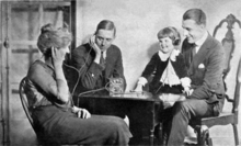
Family listening to the first radio broadcasts on a crystal radio in 1922. Since crystal radios cannot drive loudspeakers they must share earphones.
After 1920, the crystal radio became a cheap alternative radio for youth and the poor.
Cartridge carborundum detector (top) with bias battery used in vacuum tube radio from 1925
In the 1920s, the amplifying triode vacuum tube, invented in 1907 by Lee De Forest, replaced earlier technology in both radio transmitters and receivers.[70] AM radio broadcasting spontaneously arose around 1920, and radio listening exploded to become a hugely popular pastime. The initial listening audience for the new broadcasting stations was probably largely owners of crystal radios.[17] But lacking amplification, crystal radios had to be listened to with earphones, and could only receive nearby local stations. The amplifying vacuum tube radios which began to be mass-produced in 1921 had greater reception range, did not require the fussy adjustment of a cat whisker, and produced enough audio output power to drive loudspeakers, allowing the entire family to listen comfortably together, or dance to Jazz Age music.[17]
So during the 1920s vacuum tube receivers replaced crystal radios in all except poor households.[8][17][71] Commercial and military wireless telegraphy stations had already switched to more sensitive vacuum tube receivers. Vacuum tubes temporarily put an end to crystal detector research. The temperamental, unreliable action of the crystal detector had always been a barrier to its acceptance as a standard component in commercial radio equipment[1] and was one reason for its rapid replacement. Frederick Seitz, an early semiconductor researcher, wrote:[14]
Such variability, bordering on what seemed the mystical, plagued the early history of crystal detectors and caused many of the vacuum tube experts of a later generation to regard the art of crystal rectification as being close to disreputable.
The crystal radio became a cheap alternative receiver used in emergencies and by people who couldn't afford tube radios:[8] teenagers, the poor, and those in developing countries.[56] Building a crystal set remained a popular educational project to introduce people to radio, used by organizations like the Boy Scouts.[17] The galena detector, the most widely used type among amateurs,[5] became virtually the only detector used in crystal radios from this point on.[24][25] The carborundum junction saw some use as a detector in early vacuum tube radios because it was more sensitive than the triode grid-leak detector. Crystal radios were kept as emergency backup radios on ships. During World War II in Nazi-occupied Europe the radio saw use as an easily constructed, easily concealed clandestine radio by Resistance groups.[56] After World War II, the development of modern semiconductor diodes finally made the galena cat whisker detector obsolete.[56]
Development of the theory of semiconductor rectification[edit]
Semiconductor devices like the crystal detector work by quantum mechanical principles; their operation cannot be explained by classical physics. The birth of quantum mechanics in the 1920s was the necessary foundation for the development of semiconductor physics in the 1930s, during which physicists arrived at an understanding of how the crystal detector worked.[72] The German word halbleiter, translated into English as "semiconductor", was first used in 1911 to describe substances whose conductivity fell between conductors and insulators, such as the crystals in crystal detectors.[73]Felix Bloch and Rudolf Peierls around 1930 applied quantum mechanics to create a theory of how electrons move through a crystal.[73] In 1931, Alan Wilson created quantum band theory which explains the electrical conductivity of solids.[72][73]Werner Heisenberg conceived the idea of a hole, a vacancy in a crystal lattice where an electron should be, which can move about the lattice like a positive particle; both electrons and holes conduct current in semiconductors.
A breakthrough came when it was realized that the rectifying action of crystalline semiconductors was not due to the crystal alone but to the presence of impurity atoms in the crystal lattice.[74] In 1930 Bernhard Gudden and Wilson established that electrical conduction in semiconductors was due to trace impurities in the crystal, a "pure" semiconductor did not act as a semiconductor, but as an insulator (at low temperatures).[72] The maddeningly variable activity of different pieces of crystal when used in a detector, and the presence of "active sites" on the surface, was due to natural variations in the concentration of these impurities throughout the crystal. Nobel Laureate Walter Brattain, coinventor of the transistor, noted:[74]
At that time you could get a chunk of silicon... put a cat whisker down on one spot, and it would be very active and rectify very well in one direction. You moved it around a little bit-maybe a fraction, a thousandth of an inch-and you might find another active spot, but here it would rectify in the other direction.
The "metallurgical purity" chemicals used by scientists to make synthetic experimental detector crystals had about 1% impurities which were responsible for such inconsistent results.[74] During the 1930s progressively better refining methods were developed,[8] allowing scientists to create ultrapure semiconductor crystals into which they introduced precisely controlled amounts of trace elements (called doping).[74] This for the first time created semiconductor junctions with reliable, repeatable characteristics, allowing scientists to test their theories, and later making manufacture of modern diodes possible.
The theory of rectification in a metal-semiconductor junction, the type used in a cat whisker detector, was developed in 1938 independently by Walter Schottky[75] at Siemens & Halske research laboratory in Germany and Nevill Mott[76] at Bristol University, UK.[72][73][74] Mott received the 1977 Nobel Prize in Physics. In 1949 at Bell Labs William Shockley derived the Shockley diode equation which gives the nonlinear exponential current–voltage curve of a crystal detector, observed by scientists since Braun and Bose, which is responsible for rectification .[72]
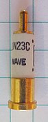
1N23 silicon diode. Grid 1/4 inch.
The first modern diodes[edit]
The development of microwave technology during the 1930s run up to World War II for use in military radar led to the resurrection of the point contact crystal detector.[8][50][74] Microwave radar receivers required a nonlinear device that could act as a mixer, to mix the incoming microwave signal with a local oscillator signal, to shift the microwave signal down to a lower intermediate frequency (IF) at which it could be amplified.[74] The vacuum tubes used as mixers at lower frequencies in superheterodyne receivers could not function at microwave frequencies due to excessive capacitance. In the mid-1930s George Southworth at Bell Labs, working on this problem, bought an old cat whisker detector and found it worked at microwave frequencies.[8][74]Hans Hollmann in Germany made the same discovery.[8] The MIT Radiation Laboratory launched a project to develop microwave detector diodes, focusing on silicon, which had the best detecting properties.[8] By about 1942 point-contact silicon crystal detectors for radar receivers such as the 1N21 and 1N23 were being mass-produced, consisting of a slice of boron-doped silicon crystal with a tungsten wire point pressed firmly against it. The cat whisker contact did not require adjustment, and these were sealed units. A second parallel development program at Purdue University produced germanium diodes.[8] Such point-contact diodes are still being manufactured, and may be considered the first modern diodes.
After the war, germanium diodes replaced galena cat whisker detectors in the few crystal radios being made. Germanium diodes are more sensitive than silicon diodes as detectors, because germanium has a lower forward voltage drop than silicon (0.4 vs 0.7 volts). Today a few galena cat whisker detectors are still being made, but only for antique replica crystal radios or devices for science education.
See also[edit]
References[edit]
- ^ a b c d e f g Braun, Agnès; Braun, Ernest; MacDonald, Stuart (1982). Revolution in Miniature: The History and Impact of Semiconductor Electronics. Cambridge University Press. pp. 11–12. ISBN 978-0521289030.
- ^ a b c d e f g Malanowski, Gregory (2001). The Race for Wireless: How Radio was Invented (or Discovered). AuthorHouse. pp. 44–45. ISBN 978-1463437503.
- ^ a b c d e f g h i j k l m Sievers, Maurice L. (1995). Crystal Clear: Vintage American Crystal Sets, Crystal Detectors, and Crystals, Vol. 1. Sonoran Publishing. pp. 3–5. ISBN 978-1886606012.
- ^ Hickman, Ian (1999). Analog Electronics. Newnes. p. 46. ISBN 978-0750644167.
- ^ a b c d e f g h i j k l m n o p q r s t u v w x y z aa ab Lee, Thomas H. (2004). Planar Microwave Engineering: A Practical Guide to Theory, Measurement, and Circuits, Vol. 1. Cambridge University Press. pp. 4–9, 297–300. ISBN 978-0521835268.
- ^ a b U.S. Patent 1,104,073 Greenleaf Whittier Pickard, Detector for Wireless Telegraphy and Telephony, filed: 21 June 1911, granted: 21 July 1914
- ^ a b c d Orton, John W. (2004). The Story of Semiconductors. Oxford University Press. pp. 20–23. ISBN 978-0198530831.
- ^ a b c d e f g h i j k l m n Seitz, Frederick; Einspruch, Norman (4 May 1998). The Tangled History of Silicon in Electronics. Silicon Materials Science and Technology: Proceedings of the Eighth International Symposium on Silicon Materials Science and Technology, Vol. 1. San Diego: The Electrochemical Society. pp. 73–74. ISBN 9781566771931. Retrieved 27 June 2018.
- ^ although at the microwave frequencies he used these detectors did not function as rectifying semiconductor diodes like later crystal detectors, but as a thermal detector called a bolometer. Lee, Thomas H. (2004). Planar Microwave Engineering: A Practical Guide to Theory, Measurement, and Circuits, Vol. 1. Cambridge University Press. pp. 4–5. ISBN 978-0521835268.
- ^ a b U.S. Patent 755,840 Jagadis Chunder Bose, Detector for Electrical Disturbances, filed: 30 September 1901, granted 29 March 1904
- ^ a b c U.S. Patent 836,531 Greenleaf Whittier Pickard, Means for Receiving Intelligence Communicated by Electric Waves, filed: 30 August 1906, granted: 20 November 1906
- ^ a b c d e f g h i j k Douglas, Alan (April 1981). "The Crystal Detector". IEEE Spectrum. 18 (4): 64–69. doi:10.1109/MSPEC.1981.6369482. ISSN 0018-9235. S2CID 44288637. archived: part1, part2, part3, part4
- ^ a b c d e f g Pickard, Greenleaf Whittier (August 1919). "How I Invented the Crystal Detector" (PDF). Electrical Experimenter. 7 (4): 325–330, 360. Retrieved 13 June 2016.
- ^ a b c Riordan, Michael; Lillian Hoddeson (1988). Crystal fire: the invention of the transistor and the birth of the information age. USA: W. W. Norton & Company. pp. 19–21, 92. ISBN 978-0-393-31851-7.
- ^ a b c Basalla, George (1988). The Evolution of Technology. UK: Cambridge University Press. pp. 44–45. ISBN 978-0-521-29681-6.
- ^ Winston, Brian (2016). Misunderstanding Media. Routledge. pp. 256–259. ISBN 978-1315512198.
- ^ a b c d e f g h i j k Sterling, Christopher H.; O'Del, Cary (2010). The Concise Encyclopedia of American Radio. Routledge. pp. 199–201. ISBN 978-1135176846.
- ^ a b c "...crystal detectors have been used [in receivers] in greater numbers than any other [type of detector] since about 1907." Marriott, Robert H. (September 17, 1915). "United States Radio Development". Proceedings of the Institute of Radio Engineers. 5 (3): 184. doi:10.1109/jrproc.1917.217311. S2CID 51644366. Retrieved 2010-01-19.
- ^ Williams, Lyle R. (2006). The New Radio Receiver Building Handbook. The Alternative Electronics Press. pp. 20–23. ISBN 978-1-84728-526-3.
- ^ Campbell, John W. (October 1944). "Radio Detectors and How They Work". Popular Science. 145 (4): 206–209. Retrieved 2010-03-06.
- ^ US National Bureau of Standards (March 1918). Circular No. 74: Radio Instruments and Measurements. Washington DC: United States Government Printing Office. p. 105.
- ^ a b c d e f g h i j k l m n o p q r s t u v Ould, Richard Sheldon (1922). The Principles Underlying Radio Communication, 2nd Ed. (Radio communication pamphlet no. 40). Written by the US Bureau of Standards for US Army Signal Corps. pp. 433–439.
- ^ a b Bucher, Elmer Eustice (1920). The Wireless Experimenters Manual. New York: Wireless Press. p. 167.
- ^ a b c d e f g h Hirsch, William Crawford (June 1922). "Radio Apparatus - What is it made of?". The Electrical Record. 31 (6): 393–394. Retrieved 10 July 2018.
- ^ a b c Cockaday, Laurence M. (1922). Radio-telephony for Everyone. New York: Frederick A. Stokes Co. p. 94.
- ^ a b c d e f g h i Stanley, Rupert (1919). Textbook of Wireless Telegraphy Volume 1: General theory and practice. London: Longmans, Green and Co. pp. 311–318.
- ^ "The cat’s-whisker detector is a primitive point-contact diode. A point-contact junction is the simplest implementation of a Schottky diode, which is a majority-carrier device formed by a metal-semiconductor junction." Shaw, Riley (April 2015). "The cat's-whisker detector". Riley Shaw's personal blog. Retrieved 1 May 2018.
- ^ a b c Lescarboura, Austin C. (1922). Radio for Everybody. New York: Scientific American Publishing Co. pp. 144–146.
- ^ Bucher, Elmer Eustice (1920). The Wireless Experimenter's Manual. Wireless Press. p. 164.
- ^ a b c d Morgan, Alfred Powell (1914). Wireless Telegraph Construction for Amateurs, 3rd Ed. New York: D. Van Nostrand Co. pp. 198–199.
- ^ a b Edelman, Phillip E. (1920). Experimental Wireless Stations. New York: Norman W. Henly Publishing Co. pp. 258–259.
- ^ Cole, Arthur B. (1913). The Operation of Wireless Telegraph Apparatus. New York: Cole and Morgan. p. 15.
- ^ Sievers, Maurice L. (2008). Crystal Clear: Vintage American Crystal Sets, Crystal Detectors, and Crystals. Sonoran Publishing. p. 6. ISBN 978-1-886606-01-2.
- ^ a b U.S. Patent 837,616 Henry H. C. Dunwoody, Wireless Telegraph System, filed: 23 March 1906, granted: 4 December 1906
- ^ a b c d e Collins, Archie Frederick (16 March 1907). "Carborundum and silicon detectors for wireless telegraphy". Scientific American. Munn and Co. 96 (11): 234. doi:10.1038/scientificamerican03161907-234. Retrieved 31 July 2020.
- ^ a b c d e f g Bucher, Elmer Eustice (1921). Practical Wireless Telegraphy: A Complete Text Book for Students of Radio Communication. New York: Wireless Press, Inc. pp. 135, 139–140.
- ^ Pierce, George Washington (1910). Principles of Wireless Telegraphy. New York: McGraw-Hill Book Co. pp. 160–162.
- ^ a b U.S. Patent 912,726 Greenleaf Whittier Pickard, Oscillation receiver, filed: 15 September 1908, granted: 16 February 1909
- ^ A. P. Morgan, Wireless Telegraph Construction for Amateurs, 3rd ed. New York: D. Van Nostrand Co., 1914, p. 135, Fig. 108
- ^ a b c d Phillips, Vivian J. (1980). Early Radio Wave Detectors. London: Inst. of Electrical Engineers. pp. 18–21. ISBN 978-0906048245.
- ^ Aitken, Hugh G.J. (2014). The Continuous Wave: Technology and American Radio, 1900-1932. Princeton University Press. pp. 4–7, 32–33. ISBN 978-1400854608.
- ^ a b Phillips, Vivian J. (1980). Early Radio Wave Detectors. London: Inst. of Electrical Engineers. pp. 205–209, 212. ISBN 978-0906048245.
- ^ Braun, F. (1874), "Ueber die Stromleitung durch Schwefelmetalle" [On current conduction through metal sulfides], Annalen der Physik und Chemie (in German), 153 (4): 556–563, Bibcode:1875AnP...229..556B, doi:10.1002/andp.18752291207
- ^ a b c Pierce, George W. (July 1907). "Crystal rectifiers for electric currents and electric oscillations, Part 1: Carborundum". Physical Review. 25 (1): 31–60. Bibcode:1907PhRvI..25...31P. doi:10.1103/physrevseriesi.25.31. Retrieved 25 July 2018.
- ^ Emerson, D. T. (December 1997). "The work of Jagadish Chandra Bose: 100 years of mm-wave research". IEEE Transactions on Microwave Theory and Techniques. 45 (12): 2267–2273. Bibcode:1997ITMTT..45.2267E. doi:10.1109/22.643830. Retrieved 29 July 2018. also reprinted on IndianDefense
- ^ a b c Sarkar, Tapan K.; Sengupta, Dipak L. "An appreciation of J. C. Bose's pioneering work in millimeter and microwaves" in Sarkar, T. K.; Mailloux, Robert; Oliner, Arthur A. (2006). History of Wireless. John Wiley and Sons. pp. 295–296, 301–305. ISBN 978-0471783015.
- ^ Sarkar, et al (2006) History of Wireless, pp. 477–483
- ^ Bose, Jagadish Chandra (January 1899). "On electric touch and the molecular changes produced in matter by electric waves". Proceedings of the Royal Society of London. 66 (424–433): 452–474. Bibcode:1899RSPS...66..452C. doi:10.1098/rspl.1899.0124. S2CID 121203904.
- ^ "Greenleaf Whittier Pickard". Encyclopaedia Britannica online. Encyclopaedia Britannica Inc. 2018. Retrieved 31 July 2018.
- ^ a b c Roer, T.G. (2012). Microwave Electronic Devices. Springer Science and Business Media. pp. 5–7. ISBN 978-1461525004.
- ^ Some biographical information on General Henry H.C. Dunwoody is available at Arlington National Cemetery.
- ^ German patent 178871 Karl Ferdinand Braun, Wellenempfindliche Kontaktstel, filed: 18 February 1906, granted: 22 October 1906
- ^ The 1911 edition of the US Navy's manual of radio stated: "There are but two types of detectors now in use: crystal or rectifying detectors and the electrolytic. Coherers and microphones [another type of coherer detector] are practically obsolete, and comparatively few of the magnetic and Audion or valve [triode] detectors have been installed."Robison, Samuel Shelburne (1911). Manual of Wireless Telegraphy for the Use of Naval Electricians, 2nd Ed. Washington DC: United States Naval Institute. p. 128.
- ^ The 1913 edition of the US Navy's manual of radio stated: "Only one type of detector is now in use: the crystal. Coherers and microphones are practically obsolete, and comparatively few magnetic and Audion or valve [triode] detectors have been installed."Phillips, Vivian J. (1980). Early Radio Wave Detectors. London: Inst. of Electrical Engineers. pp. 212. ISBN 978-0906048245.
- ^ Marconi used carborundum detectors beginning around 1907 in his first commercial transatlantic wireless link between Newfoundland, Canada and Clifton, Ireland. Beauchamp, Ken (2001). History of Telegraphy. Institution of Electrical Engineers. p. 191. ISBN 978-0852967928.
- ^ a b c d e Craddock, Christine D. (24 March 1987). "Crystal Radio: An historical survey" (PDF). Honors Thesis. Ball State University, Muncie, Indiana. Retrieved 2 August 2018.
- ^ a b Grebennikov, Andrei (2011). RF and Microwave Transmitter Design. John Wiley & Sons. p. 4. ISBN 978-0470520994. Archived from the original on 2016-09-17.
- ^ Pickard, Greenleaf W. (January 1925). "The Discovery of the Oscillating Crystal" (PDF). Radio News. 6 (7): 1166. Retrieved July 15, 2014.
- ^ a b c White, Thomas H. (2003). "Section 14 – Expanded Audio and Vacuum Tube Development (1917–1924)". United States Early Radio History. earlyradiohistory.us. Retrieved September 23, 2012.
- ^ Losev, O. V. (January 1925). "Oscillating Crystals" (PDF). Radio News. 6 (7): 1167, 1287. Retrieved July 15, 2014.
- ^ a b Gabel, Victor (October 1, 1924). "The Crystal as a Generator and Amplifier" (PDF). The Wireless World and Radio Review. 15: 2–5. Archived (PDF) from the original on October 23, 2014. Retrieved March 20, 2014.
- ^ Ben-Menahem, Ari (2009). Historical Encyclopedia of Natural and Mathematical Sciences, Vol. 1. Springer. p. 3588. ISBN 978-3540688310. Archived from the original on 2017-11-23.
- ^ a b c d e f g Lee, Thomas H. (2004) The Design of CMOS Radio-Frequency Integrated Circuits, 2nd Ed., p. 20
- ^ a b Gernsback, Hugo (September 1924). "A Sensational Radio Invention". Radio News: 291. and "The Crystodyne Principle", Radio News, September 1924, pages 294-295, 431.
- ^ a b c d e f g Zheludev, Nikolay (April 2007). "The life and times of the LED – a 100-year history" (PDF). Nature Photonics. 1 (4): 189–192. Bibcode:2007NaPho...1..189Z. doi:10.1038/nphoton.2007.34. Archived from the original (PDF) on 2017-03-31. Retrieved 2007-04-11.
- ^ Round, Henry J. (9 February 1907). "A note on carborundum". Electrical World. 49 (6): 309. Retrieved September 1, 2014.
- ^ Losev, O. V. (1927). "Светящийся карборундовый детектор и детектирование с кристаллами" [Luminous carborundum detector and detection with crystals]. Телеграфия и Телефония без Проводов (Wireless Telegraphy and Telephony). 5 (44): 485–494. English version published as Lossev, O. V. (November 1928). "Luminous carborundum detector and detection effect and oscillations with crystals". Philosophical Magazine. Series 7. 5 (39): 1024–1044. doi:10.1080/14786441108564683.
- ^ a b Schubert, E. Fred (2003). Light-emitting Diodes. Cambridge University Press. pp. 2–3. ISBN 978-0521533515.
- ^ a b Graham, Loren (2013). Lonely Ideas: Can Russia Compete?. MIT Press. pp. 62–63. ISBN 978-0262019798.
- ^ The 1918 edition of the US Navy's manual of radio stated: "There are two types of detectors now in use: the Audion [triode] and the crystal or rectifying detector. Coherers and microphones [another type of coherer detector] are practically obsolete... but the use of Audions...is increasing."Robison, Samuel Shelburne (1918). Manual of Wireless Telegraphy for the Use of Naval Electricians, 4th Ed. Washington DC: United States Naval Institute. p. 156.
- ^ The 1920 "British Admiralty Handbook of Wireless Telegraphy" stated that: "Crystal detectors are being replaced by [triode] valve detectors which are more stable, easier to adjust, and generally more satisfactory". The 1925 edition said valves were "replacing the crystal for all ordinary purposes" Phillips, Vivian J. (1980). Early Radio Wave Detectors. London: Institute of Electrical Engineers. pp. 212. ISBN 978-0906048245.
- ^ a b c d e Lukasiak, Lidia; Jakubowski, Andrzej (January 2010). "History of Semiconductors" (PDF). Journal of Telecommunications and Information Technology. ISSN 1509-4553. Retrieved 2 August 2018.
- ^ a b c d "1931: "The Theory Of Electronic Semi-Conductors" is Published". The Silicon Engine. Computer History Museum. 2018. Retrieved 1 August 2018.
- ^ a b c d e f g h Michael Riordan, Lillian Hoddeson (1998) Crystal Fire: The Invention of the Transistor and the Birth of the Information Age, p. 89-93
- ^ Schottky, W. "Halbleitertheorie der Sperrsschicht." Naturwissenschaften Vol. 26 (1938) pp. 843. Abstract in English as "Semiconductor Theory of the Blocking Layer" in Sze, S.M. Semiconductor Devices: Pioneering Papers. (World Scientific Publishing Co., 1991) pp. 381
- ^ Mott, Neville F. (1 May 1939). "The theory of crystal rectifiers". Proceedings of the Royal Society of London, Series A. 171 (944): 27–38. doi:10.1098/rspa.1939.0051. JSTOR 97313. Retrieved 3 August 2018. reprinted in Alexandrov, A. S. (1995). Sir Neville Mott: 65 Years in Physics. World Scientific. pp. 153–179. ISBN 978-9810222529.
External links[edit]
- Patents
- U.S. Patent 906,991 - Oscillation detector (multiple metallic sulfide detectors), Clifford D. Babcock, 1908
- U.S. Patent 912,613 - Oscillation detector and rectifier ("plated" silicon carbide detector with DC bias), G.W. Pickard, 1909
- U.S. Patent 912,726 - Oscillation receiver (fractured surface red zinc oxide (zincite) detector), G.W. Pickard, 1909
- U.S. Patent 933,263 - Oscillation device (iron pyrite detector), G.W. Pickard, 1909
- U.S. Patent 1,118,228 - Oscillation detectors (paired dissimilar minerals), G.W. Pickard, 1914